R203 + C201 and the R-C components in the collector of Q201 are there to make the head amp stable.Forgot the CKT, attached
RIAA in stages, either active or passive, is a compromise to get the lowest noise, the highest overload margin and the largest bandwidth, just to the designers taste.
For the second stage you should also include R209 for the two 3180 / 318 usec time constants.
R203 + C201 and the R-C components in the collector of Q201 are there to make the head amp stable.
RIAA in stages, either active or passive, is a compromise to get the lowest noise, the highest overload margin and the largest bandwidth, just to the designers taste.
For the second stage you should also include R209 for the two 3180 / 318 usec time constants.
I wish to add a rumble filter into the ckt, should this be added after the headamp or it is not sensitive to a location?
the other thing I would like to add in my simplified version is a mono blend switch:
[Ref: ]Squarespace - Please Stand By
This out-of-phase, or “null”, test, can be performed in several ways. If you’ve got a test record such as the one produced by Hi Fi News and Record Review (and I recommend it highly), then you can simply make use of the azimuth test track it provides. This test track consists of a mono signal with the left and right channels out of phase. If your preamplifier has a mono blend switch (which sums the left and right channels), you can simply play the test track, engage the mono switch, and adjust the cartridge’s azimuth until you hear minimal output through the loudspeakers.
This could be done via a switch?
Thx
4) R203 sets the feedback loop for the input amp assembly.
5) there are plenty riaa-calculation-tools around. Or make the calculations following the famous lipshitz pape https://pearl-hifi.com/06_Lit_Archive/14_Books_Tech_Papers/Lipschitz_Stanley/Lipshitz_on_RIAA_JAES.pdf
Of course you can do it in one stage, it would be another phono ckt then. Plenty of those around at diyaudio.
6) these are for loading various cartridges. They ideally like to see different inout impedances depending on model. Some believe in input-C as well, i never heard differencies with those values.
I build the HPS 4.1 it is quite complex wouldn‘t recommend it as an early project let alone changing it without knowing what goes on...
with due respect to the designer, I do not wish to give an impression that this project is any shape or form 'a beginner's' project, I take your advice, but would like to explore few possibilities in the spirit of DIY!
Find something out by accident
A few weekends ago I accidental short the –vdd and the 0v in one channel of the head amp which damage 4 jfets the OPA211 and the LMH6321.
Yesterday I fitted matched BF862 jfets to both channels and repaced the damaged OPA211 and LMH6321.
To make life easier re soldering the the OPA211 I removed C206 100nF from the pcb and forgot to refitted when I power it up.
The first thing I notice was how quick the side with the new op amp stabilised compared to the other channel, this lead me to remove the other C206 100nF (lead-lag compensation network R206/C206) and it no longer oscillating while it trying to stabilise.
Both channels are now working and stabilise quickly each channel draw a total current of +vcc 170-180mA and on -vdd 48-55mA.
I’m trying to get my head round the lead-lag compensation network R206/C206 can anyone explain why it caused the head amp to oscillate and not stabilise?
msdin
Last edited:
I did a quick SIM with LTspice.A few weekends ago I accidental short the –vdd and the 0v in one channel of the head amp which damage 4 jfets the OPA211 and the LMH6321.
Yesterday I fitted matched BF862 jfets to both channels and repaced the damaged OPA211 and LMH6321.
To make life easier re soldering the the OPA211 I removed C206 100nF from the pcb and forgot to refitted when I power it up.
The first thing I notice was how quick the side with the new op amp stabilised compared to the other channel, this lead me to remove the other C206 100nF (lead-lag compensation network R206/C206) and it no longer oscillating while it trying to stabilise.
Both channels are now working and stabilise quickly each channel draw a total current of +vcc 170-180mA and on -vdd 48-55mA.
I’m trying to get my head round the lead-lag compensation network R206/C206 can anyone explain why it caused the head amp to oscillate and not stabilise?
msdin
What I found so far is that C201 is very important to get the headamp stable, could even be a bit larger like 47pF.
I saw no positive reason for C206/R206, so your observation seems right.
Tomorrow I will spend some extra time to get to the bottom.
Hans
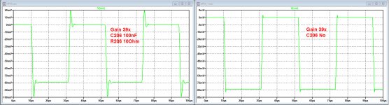
Yesterday I looked at the Head-amp with a Gain of 40, as needed for a MC Cart.
In that case, the 100nF can be discarded and has a negative impact on the step response, see first image below. Left with 100nF, right without.
In the 10x setting, as needed for an MM cart, the 100nF +10 Ohm are required for stability.
So when you are not going to use this preamp for MM Carts, you can discard the 100nF. In that case you also won't need the relay and the 47 Ohm resistors.
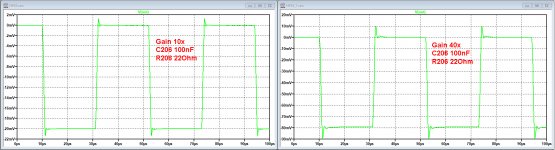
In case you want to leave the option open for using both types of Carts, I found an improvement when increasing R206 from 10 Ohm to 22 Ohm.
See second image below.
However be aware that there can always be a discrepancy between a Sim and the real thing, so you will have to test the change to 22 Ohm.
Hans
In that case, the 100nF can be discarded and has a negative impact on the step response, see first image below. Left with 100nF, right without.
In the 10x setting, as needed for an MM cart, the 100nF +10 Ohm are required for stability.
So when you are not going to use this preamp for MM Carts, you can discard the 100nF. In that case you also won't need the relay and the 47 Ohm resistors.
In case you want to leave the option open for using both types of Carts, I found an improvement when increasing R206 from 10 Ohm to 22 Ohm.
See second image below.
However be aware that there can always be a discrepancy between a Sim and the real thing, so you will have to test the change to 22 Ohm.
Hans
Attachments
One other observation that I had, was the sensitivity for the value of the eight coils at the Fet inputs.
My model became instable in both gain settings and started oscillating near 100Mhz when exceeding a value of 0.1uH.
So the advised 1uH might be too much !
It will be beneficial having a scope available to test all this.
Hans
My model became instable in both gain settings and started oscillating near 100Mhz when exceeding a value of 0.1uH.
So the advised 1uH might be too much !
It will be beneficial having a scope available to test all this.
Hans
Yesterday I looked at the Head-amp with a Gain of 40, as needed for a MC Cart.
In that case, the 100nF can be discarded and has a negative impact on the step response, see first image below. Left with 100nF, right without.
In the 10x setting, as needed for an MM cart, the 100nF +10 Ohm are required for stability.
So when you are not going to use this preamp for MM Carts, you can discard the 100nF. In that case you also won't need the relay and the 47 Ohm resistors.
In case you want to leave the option open for using both types of Carts, I found an improvement when increasing R206 from 10 Ohm to 22 Ohm.
See second image below.
However be aware that there can always be a discrepancy between a Sim and the real thing, so you will have to test the change to 22 Ohm.
Hans
Hi Hans,
I will try changing resistor (R206) 10ohms to 22ohms to see if it work.
Having so far tried increasing (C201) from 22pF to 66pF by stacking two more 22pF the original problem with it oscillating was still there.
One other observation that I had, was the sensitivity for the value of the eight coils at the Fet inputs.
My model became instable in both gain settings and started oscillating near 100Mhz when exceeding a value of 0.1uH.
So the advised 1uH might be too much !
It will be beneficial having a scope available to test all this.
Hans
The Jfet front end looks just like a Hartley oscillator would it be better to change the 1uH inductor for a gate stopper resistor?
msdin
Hi Hans,
I will try changing resistor (R206) 10ohms to 22ohms to see if it work.
Having so far tried increasing (C201) from 22pF to 66pF by stacking two more 22pF the original problem with it oscillating was still there.
The only remedy to stop oscillating is to lower R206.
That will ruin the low noise figure.The Jfet front end looks just like a Hartley oscillator would it be better to change the 1uH inductor for a gate stopper resistor?
msdin
Hans
Connecting a simulated MM Cart (580mH + 460 Ohm) in the 10x gain setting gave no problem with 1uH Coils.
But a low impedance source (high output MC) in the 10x position gave immediate trouble resulting in oscillations in this gain setting.
When having trouble with oscillations, first try to lower the 8 coils to 10 nH.
When this does not sort any effect, try to lower R206 to 5 Ohm.
Avalue of 100nF /5 Ohm seemed to be working in all cases with several different Op-Amps, but in most cases this will not be needed.
In case of using the OPA 211, I measured 41nV noise from 20Hz to 20 Khz, equalling 0.29nV/Hz^½ input noise.
Using a 4.5nV/Hz^½ Op-Amp resulted in a slightly increased 0.35nV/ Hz^½ input noise.
So to conclude, in the 40x Gain setting C206 seems not to be needed in most cases, but is mandatory when using the 10x Gain.
C201 can be better set to 47pF, just as specified in the original documentation.
When using an MC cart, simulations suggest not using more than 10nH for the 8 input coils.
An MM Cart can very well use up to 1uH input coils.
Hans
Below is the LTspice IV model that I used, for those wanting to experiment themselves.
The OPA211 is modelled with "UniversalOpamp2" and the LMH6321 is a sub circuit, an exact copy using discrete transistors.
There are a few Op Amps at the side that can be used to compare overall transfer behaviour to the OPA211.
In the 40xGain setting, max output is 8.5 Veff, resulting in 32.5 dB overload margin at 20 Khz for an MC, an excellent figure.
This limit is caused by the 300mA max that the LMH6321 can deliver into 40 Ohm.
In the 10x setting however, this buffer sees 10 Ohm, so max output drops to 2.13 Veff, giving only 12.6 dB overload margin for an MM at 20Khz.
Music will never be that loud at 20Khz, but pops and clicks are, so 12dB is definitely too low for a high quality head amp.
This marginal overload problem can easily be cured by leaving the feedback resistor 39 Ohm at all times, but to replace R227 by 1 Ohm+3.3 Ohm, where the 3.3 Ohm is shorted in the 40x setting.
4.3 Ohm + 39 Ohm instead of 1 Ohm + 9 Ohm will increase the overload margin for an MM from 12.6dB to a substantially higher 25.2 dB.
The equivalent input noise will rise from 41 nV to 56 nV in the 10x setting because of the now increased value of R227, but given the fact that an average MM with 580 mH and 460 Ohm, terminated with 47 Kohm, already produces 2.9 uVnoise, the increased head amps input noise from 41 nV to 56 nV is completely insignificant.
R227 could even be further increased to enlarge the distance between the two gain settings like 40x and 4x, instead of the current 40x and 10x.
Having 20dB between MC and MM setting corresponds more to what’s usual.
Hans
Attachments
I used LTSpiceIV because it includes the BF862 in "Bipolar Transistors.Lib" in the LTSpiceIV\Lib\Sub directory.
Copying this .lib to LTSpiceXVII in the same Lib\Sub did not work.
However when copying this .lib from LTSpiceIV into the same LTSpiceXVII directory as your HPS5.asc model, it will work.
And not even that, it works better and much faster as in LTSpiceIV.
I have included this .lib file below.
Hans
Copying this .lib to LTSpiceXVII in the same Lib\Sub did not work.
However when copying this .lib from LTSpiceIV into the same LTSpiceXVII directory as your HPS5.asc model, it will work.
And not even that, it works better and much faster as in LTSpiceIV.
I have included this .lib file below.
Hans
Attachments
OK, so after about 6 years my HPS5.1 blew up. The LMH6321 blew up destroying the PCB in the process. It looks like the positive 17 volt rail got to output 21V.
Does anybody have an extra PCB they can sell me?
Preferably one with solder-stop. If not the gerber files would also help me since the website does not load for me.
Thanks guys
Does anybody have an extra PCB they can sell me?
Preferably one with solder-stop. If not the gerber files would also help me since the website does not load for me.
Thanks guys
Last edited:
OK, so after about 6 years my HPS5.1 blew up. The LMH6321 blew up destroying the PCB in the process. It looks like the positive 17 volt rail got to output 21V.
Ouch

Don’t you fancy building syn06’s latest iteration in the HPS series of phono amps (6.1)? See here.
Ouch
Don’t you fancy building syn06’s latest iteration in the HPS series of phono amps (6.1)? See here.
Or even HPS 6.2 that can be battery powered (if needed), with a minimal noise penalty
. Much simpler and, as a result, a significantly smaller board. That's what I am myself currently using.https://www.diyaudio.com/forums/analogue-source/333000-hps-6-1-a.html#post5703900
https://www.diyaudio.com/forums/analogue-source/333000-hps-6-1-a-2.html#post5707317
For the HPS 6.x, 95% of the parts can be re-used. HPS 6.x have all the solder mask and silk screen included.
Last edited:
Ouch
Don’t you fancy building syn06’s latest iteration in the HPS series of phono amps (6.1)? See here.
Ohhh, i had no idea there was a new version of it
Thank you for telling me about it since the old one had stability problems so i might build the new one instead The board is smaller so cheaper and it looks like the head-amp has a completely new configuration.Has anyone built both HPS5.1 and HPS6.1? How do they compare from a thermal stability point of view and sound wise?
Last edited:
- Home
- Source & Line
- Analogue Source
- Hps 5.1