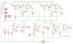
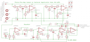
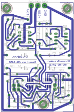
A phono preamp circuit and pcb design based on Application note AN-1651
was put in analogue sources forum sometime back. Here is the almost
final version of the design together with a suitable power supply. Suggestions
are still welcome. There was a request from a forum member for the gerber
files of the pcb design. As I make pcb in home using iron-pressing method,
I am not familiar with all the parameters the CAM processor in eagle asks for.
If someone tells me about it I can process the gerber files and post them
here.
Also there was a suggestion to make a switchable subsonic filter out of the
unity gain output buffer in the premap circuit. As I still could not figure
out how to do it in the best possible way, I left it as it was before.
Regards
Roushon
Attachments

Q: Why have a seperate power supply. IC1+2 are just that. You need between +/-15 to 22 VDC on your PAD1 and 2 and common.
Again about the common connections on the preamp board. I would go from component to component. On the "top" of the board you star 8 parts, on the "bottom" 10. I would daisy-chain them as much as possible. As I mentioned before: star grounds are necessary only when the ground is carrying a load.
Gerber files are generated by your PCB design program. I am not familiar with what program you use.
A sub-sonic filter is simply a capacitor at the output (PAD19) with an on/off switch across, followed by a resistor to common. The calculation of values must include the input resistance of the following amplifier
Thanks for your critical look at the design.
1. The application note an-1651 does not say if the circuit needs a
regulated or unregulated supply, so I thought to be on the safe side
make a regulated one. I have seen other people making regulated supply
for this circuit in this note. I understand your point and thought about it.
In that case I can even place the power supply on the same board. This will
make whole project compact.
2. To connect all the ground end it is better for me to make the board
double sided and connect all the ground to a single point on the
component side. (There is another solution keeping it single sided, by
rotating the upper part of the board 180 degree and then placing
on the side of the lower part, but the free version of the eagle program
I am using does not allow a big board.) I will try this, then together
with the PS everythig will be on the same small board.
3. Regarding the subsonic filter do I have to add the (switchable) cap
at the output or the input of the buffer? I knew I have to add it
on the input (that is pin 5 of IC4).
Regards
Roushon.
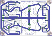
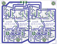
the pcb incorporating the sub-sonic filter
The PCB now contains the sub-sonic filter circuit and also differently designed
following suggestions by mickeymoose. I could place the PS also on the same
board, but as I will have the same PS for both the channel, the PS board will be
separate.
Regarding gerber file I look at the sources now.
Thanks and regards
Roushon
Attachments
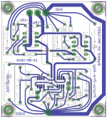
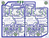
both channel on the same board
The PCB containing both the channel is below. Also the pdf files of the actual size PCBs are
attached in case someone would like to make it in home. The red tracks indicate
jumpers.
Roushon
The PCB containing both the channel is below. Also the pdf files of the actual size PCBs are
attached in case someone would like to make it in home. The red tracks indicate
jumpers.
Roushon
Attachments
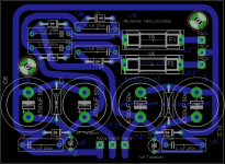
Final pcbs of the preamp and ps going to etch....
There is not much difference in the preamp pcb, but the
ps board has no regulators now.
Roushon.
There is not much difference in the preamp pcb, but the
ps board has no regulators now.
Roushon.
Attachments
Some time ago I also biuld some phono preamps and learned that it's difficult to make a good one.They have a high gain and because of this are very noisy and if you are unlucky hum can also be a problem.
Besides I think it's better to use a regulated power supply.
I also thought in this way and designed a regulated power
supply (post number 1). But mickeymouse argued in
post number 2 that the top two ics are regulating the
power supply for the preamp (bottom ics). Did you make
exactly the same circuit as in the application notes? I am
eager to know as you have experienced some problem.
But not sure if you made the top part of the circuit.
Thanks and Regards
Roushon.
I have no experience with this circuit, but similar one from this site:
Hi-Fi RIAA Phono Preamp
The preamp in the Application note AN-1651 there are two versions.One is complete passive and other active/passive.And they are designed for moving coil pickups and not the standard moving magnet type phono pickup.There is no power supply regulation.
And here you can read about the cartriges.
http://en.wikipedia.org/wiki/Magnetic_cartridge
Last edited:
Possible is this of course, but you need to change the overal gain because moving-coil cartridges generate an even lower voltage signal than a moving-magnet type cartridge. This is because the moving coil cannot be large enough (it would be too heavy) to generate equivalent voltage levels. The resulting signal is only a few hundred microvolts, and thus more easily swamped by noise, induced hum, etc.
And I think the two op-amps at the top of the circuit are for the regulated power supply.It's done by op-amps and not by ic regulators.I think you can drop them and all associated parts and use lm337, lm317 instead.It will be simplier and cheapier also.You need then only three LME49710
And I think the two op-amps at the top of the circuit are for the regulated power supply.It's done by op-amps and not by ic regulators.I think you can drop them and all associated parts and use lm337, lm317 instead.It will be simplier and cheapier also.You need then only three LME49710
Last edited:
Thanks again
Thanks Leon for opening my eyes. I can remove the dc servo completely as
I already have a cap on the signal path in the amp and also there
is dc servo in the main amp (LM3886). Regarding MM/MC cartridge I am
unable to decide now as I do not have the TT yet so do not know
which type of cartridge it will have. I have planned Project Debut III which
has MM type I think. The supplier will inform me in few weeks what
will they get (import).
Can I replace the NE5532 IC in your referred circuit by LM4562/AD8620? As I
already have these ICs. I think I can, but asking just in case.
Regards
Roushon.
There is also some other designs wich may be interesting for you.
Here is one Hagerman Technology LLC: Bugle Opamp Moving Magnet Budget Phonostage DIY Kit
Here is one Hagerman Technology LLC: Bugle Opamp Moving Magnet Budget Phonostage DIY Kit
Thanks
Thanks!
Regards
Moved to analog source for more phono people to easily see.
Thanks!
Regards
There is also some other designs wich may be interesting for you.
Here is one Hagerman Technology LLC: Bugle Opamp Moving Magnet Budget Phonostage DIY Kit
Thanks again. I did see this site before. In fact the PS
unit idea (before regulator) I got from there. But the preamp
circuit says it is partial. I am not sure what is missing there.
I do not expect a complete circuit as they sell product.
Regards
Roushon.
- Status
- This old topic is closed. If you want to reopen this topic, contact a moderator using the "Report Post" button.
- Home
- Source & Line
- Analogue Source
- Phono-pre-amp+power supply pcb