Quote all you say, Niffy - which is one of the reasons to draw these arms: experience led me to think that arms and ball bearings hate working together.
The jewels are fascinating, but even if the 3DTOY of a toy has only the color, I do not think they are suitable. First because jewels are high precision mechanisms and here instead loads are not in axis, and second because when the arm is handled the stresses can be harsh.
In this new arm I use a threaded rivet as seat of the cup grain, and this because threaded plastic can not withstand continuous adjustments (normally unuseful, just set up the grain and brake it with a drop of loctite)
Hollow infill is introduced by the "slicer" program (eg CURA or SLIC3R) for printing - different shapes and densities can be set - Maybe the effect is to split resonances in thousands different frequencies.
carlo
I look forward to seeing further development. - join us for that, please, your skill & experience will be precious
Hi Carlo
With your arm the main load, the mass of the arm, WILL mainly be axially aligned with the bearings. There will be a torsional element due to the cantilevered style of construction. Stylus drag will be insignificant. With my arm the load is almost exactly at 90° to the axis of the bearings and yet they still function flawlessly. I have had no issues regarding the ruggedness of the bearings during normal use or set up/alignment. Many manufacturers use jewelled bearings with tungsten carbide pivots, Graham, origin live, thales to name a few. Commercial arms have to be Trump proof in their ruggedness.
The small amount of give inherent in the 3D printed components will make adjusting the bearings relatively easy. My bearings are mounted in acrylic blocks which is admittedly harder than most printable plastics. I have had no issues despite multiple bearing swaps and adjustments. The addition of threaded inserts would solve this problem and would probably act to improve mechanical grounding.
Don't write off jewelled bearings, they would be the final icing on the cake.
Niffy
Has a "reduced" tracking error tonearm ever been tried?
What I am thinking of, is using the average time for a side of a record, and moving the arm base across at a steady rate to keep the arm on average approximately tangential. It would be fairly easy to achieve, and could be done with reasonable structural integrity.
What I am thinking of, is using the average time for a side of a record, and moving the arm base across at a steady rate to keep the arm on average approximately tangential. It would be fairly easy to achieve, and could be done with reasonable structural integrity.
new??
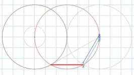
Found this: follows the Thales circle, moves parallel, is feasible. For now seems completely useless for our goals, but who knows...
carlo
Jewel bearings - Graham, Origin live, Thales ...
I know they are at top, Niffy, but the plastic 3D TOY is completely another tale. Add that the cantilever is 2.5 times the height, so the torsion is relevant: maybe better to rely to the spherical joint of a ball pen nib, than to an improper side friction.
thanks - carlo
Attachments
new?? - 2
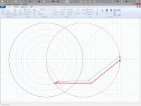
Well, not completely useless (attachments)
After the Syrinx fail i never gave up with the "extensible arm" Thales solution: this is very far from a real working tonearm (3 pivots+string link are beyond my taste), needs more geometric refinement, but maybe deserve to be further investigated.
ciao carlo
Attachments
On the extending arm idea. I'm not entirely happy with a design that relies on stylus drag to power the extension of the arm to keeps the cartridge aligned.
With a modestly eccentric record, where the cartridge has to move the back and forth by half a millimetre, the arm will spend only about 54% of the time moving to the left and 46% moving to the right. When moving to the right to arm has to shorten against the pull of the stylus. The only other force acting is the side force on the stylus due to the movement of the groove, the same side force that moves the arm in a conventional pivoted arm. This side force will have to now both move the arm to the right and shorten the arm against the pull of the stylus. This will of course require a greater side force.
Ideally the side force required to move the arm should be equal for movement both to the left and to the right. The magnitude of the side force, of course, needs to be as low as possible hence the search for ultra low friction bearings.
Niffy
Thanks, Niffy, for pointing out the eccentricity issues. Maybe there are much greater problems around: all those joints - a nightmare - the points of application of the forces, far from ideal.
Don't know if it can work, but I was so pleased to finally find an extensible arm without linear bearings that I could not resist to post it.
Only geometry, for now
carlo
Don't know if it can work, but I was so pleased to finally find an extensible arm without linear bearings that I could not resist to post it.
Only geometry, for now
carlo
3d toy
I've been reading this thread backwards until i saw the post with the 3d toy design files. I think it's amazing and I think it will be fun to build a copy but i can use some guidance with the 3 printing, which is new to me. So question no1: is PLA a good choice or do i need something more sophisticated?
And no2 about the arm wand. It says 6*5 tube, what does it mean? I'm assuming 6 mm dia 0,5 mm wall thickness but i'd like to be sure before sourcing the parts. More questions will follow in the learning curve. TIA and goodbye for now.
Vincent
Hi Vincent, glad that 3DTOY interested you. Even if called toy, keep in mind that PLTs, like linear trackers and more, must be built very well to work.
If you are new to this thread start from the beginning: you will find there the basic problems and solutions, discussed in the most complete way. Explore carefully all the Birch type saga, to understand the problems we are facing: better before than after.
Construction - as I said, the most difficult work are the ballpen tip bearings - begin from there (see the 3Drabbit drawings too)
3d printing - PLA is ok, there are stronger materials but it is easier to have distortions, to be avoided absolutely. On web you will find lots of infos: take care of the settings for the shell (4 -6 times the nozzle) and the infill (30-40%). You will find two types of bases: the one I use (with a 16mm tube) that can be reduced to a simple plate, or a SME standard. Feel free to modify all the files to your needs.
Wand - use what you like, but light & sturdy. (6x5 are outer and inner diameters). What is instead essential are the cables: if they are not really thin and soft you'll get troubles
Have fun - carlo
Thanks Carlo, for the extensive reply. I've build a linear tracker before and the wiring was the biggest problem indeed. I'll study the different solutions in the thread for now that's more then enough reading I guess. One other thing is with the previous arm there was free movement back and forth possible because of the construction. I'm not sure how this is with these arms and if it's a real problem. Which one do you prefer, the belt driven or the one with the parallel bars?
Hi All
Check this out.
YouTube
I've calculated all the forces and it looks like it will work fine.
There are 2 systems in the body for lateral translation, 1 in balance with 2 jewel bearings of which only 1 is loaded. The other bearing is a support.
The second system is not a balanced system but a variable velocity rotation mechanism that changes the output velocity of the shaft the tonearm hangs from. Uses 4 jewel bearings only 2 loaded.
The simulated forces look very good and the starting torque is less than the stylus drag force ~0.0009N (ideal simulation).
It looks like it might be possible to build, but the tolerances are very tight.
Only way to be sure is to build and test the starting torque.
Build weight as designed is about 130g but that can be cut by at least 50%, this will have a major effect on the starting torque.
Tonearm length 150mm
There is only 1 NULL point, and it is everywhere.
Carlo did say there had to be curves to be found and there were.
Only worry is transmission losses IRL.
2wice,
You've got my attention. Two cams? Sure would like to see a plan view.
I'm not yet ready to share the internals publicly as it was a lot harder than I thought, but if you PM me your email I can send you a look.
Which one do you prefer, the belt driven or the one with the parallel* bars? Vincent
... the next i'll build: always trying to experiment, not to make the $$uper-reference-definitive arm at home.
There is only 1 NULL point, and it is everywhere.
Welcome back, 2wice. and with such a sophisticated solution (geometry and mechanics) - eager to understand how it works
carlo
* no. not parallel: it took a lot of work of Doug, 2wice and me to find the best levers ratio (measures on the linkage file)
Last edited:
Welcome back, 2wice. and with such a sophisticated solution (geometry and mechanics) - eager to understand how it works
Thanks, I will share once I know it works for sure.
There is still an eccentric issue, if I can counter the drag force somehow that "problem" will disappear. It can be done with a counterweight but that just seems a bit clunky and approximate.
Last edited:
Your question intrigued me
Hello midrange,
You made me curious, so I made some CAD drawings to find out just how much tracking error there would be.
The minimum and the maximum groove pitches are .002" and .010" respectively. I assumed a lead screw pitch of .006" (the average) rotating at the same RPM as the LP to keep the math simple.
Drawing 1 shows a tracking error of + and - 12.425 Degrees on an LP having all grooves at the .002" pitch.
Drawing 2 shows a tracking error of + and - 12.426 Degrees on an LP having all grooves at the .010" pitch.
Now, if you had an LP with alternating .002" and .010" pitch grooves, you would have no tracking error.
Depending upon what combination of groove pitches a particular LP may have, you would get unpredictable tracking errors between 0 Degrees and 12.425 Degrees.
Sincerely,
Ralf
Has a "reduced" tracking error tonearm ever been tried?
What I am thinking of, is using the average time for a side of a record, and moving the arm base across at a steady rate to keep the arm on average approximately tangential. It would be fairly easy to achieve, and could be done with reasonable structural integrity.
Hello midrange,
You made me curious, so I made some CAD drawings to find out just how much tracking error there would be.
The minimum and the maximum groove pitches are .002" and .010" respectively. I assumed a lead screw pitch of .006" (the average) rotating at the same RPM as the LP to keep the math simple.
Drawing 1 shows a tracking error of + and - 12.425 Degrees on an LP having all grooves at the .002" pitch.
Drawing 2 shows a tracking error of + and - 12.426 Degrees on an LP having all grooves at the .010" pitch.
Now, if you had an LP with alternating .002" and .010" pitch grooves, you would have no tracking error.
Depending upon what combination of groove pitches a particular LP may have, you would get unpredictable tracking errors between 0 Degrees and 12.425 Degrees.
Sincerely,
Ralf
Attachments
Hi Doug - to draw and edit I'm using - Freecad - (boolean), my friend instead uses - Blender - (mesh); for slicing to print - Repetier - or others. Complete and reliable, all free and also for Mac.
I've modified the 3drabbit files, and maybe now are ok - for now I can not print and test, but if you want i'll post them.
ciao carlo
I've modified the 3drabbit files, and maybe now are ok - for now I can not print and test, but if you want i'll post them.
ciao carlo
- Home
- Source & Line
- Analogue Source
- Angling for 90° - tangential pivot tonearms