Hi Ray,
What about with a dc motor? I tried this method to determine the hysteresis loss in the belt on my dc driven deck but didn't get it to work.
Niffy
Mmm.. good point. In principle, current in a pure DC motor should be linearly proportional to load. IME we attached a strain gauge to a 1,000 HP DC motor on a plastic extruder drive and compared shaft torque to motor current. It was a straight line linear relationship. But how many turntable drive motors are pure DC? A brushless DC motor or electronically commutated DC motor might not be so linear. Monitoring motor current as a 'wiggle' meter could be useful, but to accurately measure the power consumed by stylus drag would require controlling and isolating numerous variables, IMO not so simple to do.
Ray K
You are right. I quicly measured the current draw with a plug-in Silvercrest power meter on my Thorens TD-160S. Voltage = 230V, Current = 0.009/0.0010A, power factor = 1.0, no change with and without stylus on discNot quite. Power = Voltage x Current x Power Factor.
 I will try with a handheld meter in 200mA range, assuming constant voltage and cos φ = 1.
Niffy: You can of course perform tests on both lightly and heavily modulated sections in order to set upper and lower averages. For most design purposes this is adequate. The peek levels of stylus drag, due to sudden loud transients, will be higher than this average. Also this test will not give any information on events such as the transition from a loud passage to quiet or vis versa.
In my tests I tried to contain the problem by carefully choosing the piece of music; pre-Romantic symphonic music without peaks or excessive high or low band contents
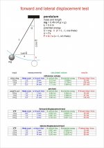
Test conditions: really common -
medium mass platter (2.7kg) cheap AT95 cartridge with VTF 2.0 gr; average classic orchestra musical content, with no peaks. - 200mm circle track - (....)
How it works: as hoped, it is a pleasure to finally see with our own eyes these small forces amplified by the pendulum; for example it can be seen even the variation due to a variable musical content.
Tracing other tracks with relevant variations, the rig highlights the change in friction, but still with small movements of 1 -2 mm (10 - 20% ) a higher percentage with a minor VTF.
The method of stopping down has many merits but, for my taste, introduces too many parameters difficult to measure; the engine engaged multiplies them, maybe.
I've tried instead a "direct" method using a device very simple to build and with negligible friction. Living in Tuscany, where Galileo was born, a pendulum comes to mind naturally. Don't know if the rig actually measures the displacement caused by the stylus drag (you can enlighten me). I know that - repeating them several times - the measurements are consistent.
If you have a little time, build it: it's simple and ... therapeutic.
Carlo
In my tests I tried to contain the problem by carefully choosing the piece of music; pre-Romantic symphonic music without peaks or excessive high or low band contents
Test conditions: really common -
medium mass platter (2.7kg) cheap AT95 cartridge with VTF 2.0 gr; average classic orchestra musical content, with no peaks. - 200mm circle track - (....)
How it works: as hoped, it is a pleasure to finally see with our own eyes these small forces amplified by the pendulum; for example it can be seen even the variation due to a variable musical content.
Tracing other tracks with relevant variations, the rig highlights the change in friction, but still with small movements of 1 -2 mm (10 - 20% ) a higher percentage with a minor VTF.
The method of stopping down has many merits but, for my taste, introduces too many parameters difficult to measure; the engine engaged multiplies them, maybe.
I've tried instead a "direct" method using a device very simple to build and with negligible friction. Living in Tuscany, where Galileo was born, a pendulum comes to mind naturally. Don't know if the rig actually measures the displacement caused by the stylus drag (you can enlighten me). I know that - repeating them several times - the measurements are consistent.
If you have a little time, build it: it's simple and ... therapeutic.
Carlo
11.1mA, stylus drag has no effect (or the resolution is too low).I will try with a handheld meter in 200mA range, assuming constant voltage and cos φ = 1.
Another method for measuring the friction force: take an angled tonearm, measure the force applied by your antiskating device, the rest can be calculated from geometry.
Edit: I see it does not work for a linear tracker. But the result is transferable from an S-arm to an LT using the same pickup.
Edit: I see it does not work for a linear tracker. But the result is transferable from an S-arm to an LT using the same pickup.
Last edited:
Lots of interesting and inventive ways to measure stylus drag. As stylus drag is such a variable phenomenon measuring it to more than one significant digit is probably unnecessary. Having an overall average is probably the most useful figure. Average drag for unmodulated and heavily modulated tracks add extra detail and are the figures I tend to use myself. Having a more dynamic representation of what's going on, especially in respect to peek values, would be very interesting. I've not seen peek values reported from other tests. I'm certainly hoping that Carlo manages to measure some dynamic behaviour.
With an LT arm stylus drag doesn't really matter. I did contemplate angling the wheels on my mechanical LT arm so the combination of weight and drag would be normal to the rail. I didn't bother as the angle would have been too small to make any difference.
(stylus drag will theoretically effect VTA as the pull is horizontal but the tracking angle is inclined by about 20°. The difference in VTA between modulated and unmodulated would typically be about 0.35°. This may seem a lot but if VTA is set correctly at high modulation then the maximum error would be when there is no modulation, hence no sound so you couldn't hear it. [Quick calculation disclaimer though I did calculate in two different methods to double check, tension and torsion] )
With a conventional pivoted arm stylus drag directly results in skating force which is a problem that require cancellation with anti-skate. Simple anti-skate mechanisms just apply an average. More sophisticated setups vary depending upon the position across the record. With a fixed offset the amount of skating force increases slightly towards the middle of the side then slightly decreases towards the run out groove. (actually inverse to the tracking angle)
With most pivoted tangential tracking arm the skating force tends to decrease as the stylus tracks inwards. It is preferable to have an anti-skate that decreases in line with this. On the whole the average amount skating force for a tangential arm is about the same as a conventional pivoted arm of the same length.
Several designs of tangential arms attempt to use stylus drag as the motive force required to change the geometry of the arm and maintain tangency. I don't think that this is a good idea. Due to eccentricity the arm spends a large amount of the time moving from left to right. When moving to the left stylus drag elongates the arm. However when moving to the right the arm needs to shorten but drag is still pulling against this. Any good arm should be able to play a record cut from the inside out as well as it does a normal record. (i actually have a record store day special cut like this) If you have a system that centres the record then having an arm that only plays right to left is ok.
Carlo. I notice that when you performed the side force test you had your scales oriented vertically. My scales just read error if I try this. This really simplified how you can adapt your rig to make direct measurements. Mount your scales vertically. Run a thread from the rear of the pendulum directly to the scales, attach with a bit of tape. Tension due to stylus drag will be coupled directly to the scales.
With any measurement you want all conditions to be as similar to when actually playing a record as possible. When playing a record you know something is seriously wrong and conditions not normal if the stylus skips. If your test rig skips you know that there is something happening that is very different to normal record play. Any readings made under these conditions are likely to be inaccurate.
Fascinating investigation. Looking forward to your conclusions.
Niffy
Dear Niffy, what you suggest is more or less the method that followed Doug for the side force? (headshell pushing a digital scale - pulling in your hypothesis). Good, but at that point what is the use of the pendulum? you should calculate the resistance of the scale + that of the pendulum, a real mess.
The reason why I did not use the digital scale is that while with the friction of the linear bearing of Syrinx (0.25 g) it worked well, with the second arm (friction <0.1 g) results were random. With that very small resistance the arm was barely moving on the disk, and so I knew I would have to measure forces of that order, not 2 gr.
The pendulum is the simple and marvelous tool that allowed to measure the gravity and rotation of the earth 500 years ago. Strain gauges are maybe better: is anyone out there able to use them?
Carlo. The notice that you performed the side force test you had your scales oriented vertically.
No image of the side displacement (amusing from my point of view) yet posted.
If I put measurement scales for the angle and the displacement is because with L = 40 cm an angle of 1 ° - perfectly observable - corresponds to an elevation of 0.06 mm***: a little difficult to make scales in hundredths of mm. Also, observing a Work, we need to know the displacement to calculate the Force.
When playing a record you know something is seriously wrong and conditions not normal if the stylus skips.
Maybe you did not understand what happens (my English is terrible, I know)
Test is about the normal behavior of a stylus up to the point of breaking. In the forward movement it happens like when you try to climb a slope with the wrong shoes: when it becomes steeper, you can not go forward and sometimes you start sliding backwards; the stylus advances until the inclination of the pendulum equals friction, the stylus then slides back 1 - 2 mm (probably not in the same groove). So I think that, at least for my needs (understand why the Syrinx and the other did not work) measures and calculations are adequate
Fascinating investigation. Looking forward to your conclusions
I hoped that calculations and conclusions on my observations (repeatable by anyone with little effort) would be posted by someone more qualified than me, but since it does not happen, will be posted toghether witht the side displacement test. It will only be the opinions of one who tries to make real arms.
Several designs of tangential arms attempt to use drag as the motive force required to change the geometry of the arm and maintain tangency. I do not think that this is a good idea.
You're probably right, but the eccentricity is just a little problem, not the real reason (if the eccentricity is not disgusting all the cartriges manage it with a little bit of stylus bending before moving the horizontal mass or worse the damping of the arm - use a macroscope and you will see it with your eyes). The real reason belongs to stylus drag itself-
Ciao Carlo
*** that's why a pendulum works so well to measure so small forces
Last edited:
Hi Carlo,
Thanks for the clarification. I fully agree that a pendulum can make measuring small forces much easier than trying to read a dancing digital display, that's why I adopted it for my side force measuring rig. I think I completely misunderstood what you meant by skipping.
Niffy
Thanks for the clarification. I fully agree that a pendulum can make measuring small forces much easier than trying to read a dancing digital display, that's why I adopted it for my side force measuring rig. I think I completely misunderstood what you meant by skipping.
Niffy
homework 2:
lateral displacement test
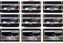
I had to change the layout of the post 1548 because a certain twist altered the measure and a uniform adjustment of the 4 strings was really problematic. Now a 15" - 0 offset tonearm, assembled with syrinx pieces pushes the pendulum trough a needle on the headshell. This brings a bit more friction.
The lateral displacement occurs until skipping.
test conditions: same as the previous test - for the data refer to the summary table and photos attached
Conclusions
Fascinating investigation. Looking forward to your conclusions (Niffy)
I hoped that calculations and conclusions on my observations (repeatable by anyone with little effort) would be posted by someone more qualified than me, but since it does not happen, will be posted toghether witht the side displacement test. It will only be the opinions of one who tries to make real arms. post #1587
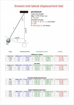
Pre test:
The calculated values (0.34> 1.3) from these observations are lower than the theoretical ones (0.5> 2 gr) of about 30% (pulley friction, etc). Therefore, the reference values that could be observed with the theoretical drag stylus should be 30% higher, as those shown in the first table
Forward displacement test
the observed values (0.2> 0.45) are always below the theoretical values calculated both with the friction coefficient (0.5> 2.0) and the stopping method (04> 1.0).
The difference is significant, but could still derive from instrumental errors in this test, as in the others mentioned (we are measuring minimal and variable values).
However, this difference is crucial in practice, because with 2-300 mg it is very difficult to win the stiction of a linear bearing, and my two tonearms are unfortunately the proof. This makes some types of PLT arms (extensible Thales - tricycle and variants) almost unfeasible (at least by me) without advanced technologies and materials often mentioned in this and other threads. Unfortunately only mentioned.
Anomalies --- The force seems to depend on the VTF, but maybe the relative coefficient of friction is variable: the motion of a stylus is so complex that I dare not to say anything.
The force on external grooves seems much lower than on middle ones, and this is even more surprising (outer skating is greater because etc). Perhaps the friction also changes with the peripheral speed. More tests will be needed
Lateral displacement test
The values observed are always larger than those of forward displacement.
It must be said that this force (let's call "skipping force"), increasing groove after groove from 0 to breaking point is only the maximum available to move an arm (for that VTF and cartridge). Every arm hopefully uses just the fraction necessary to overcome the resistance of the constraint (pivot or carriage), for our cartridge's health.
It remains the problem of how this "mysterious" force is generated, and that must be leaved to physicists. Better not examining only the first groove....
Happy ending - Many will find these tests on so well discussed topics useless and childish; but I needed to see (and measure) the action in the real world of those elusive forces, anf this toy allows it. If I had done it before I could have avoided the construction of two useless arms, built on hearsay knowledge: instead those two big mistakes were needed to build this toy.
ciao a tutti - Carlo
Doug: my data are something smaller than your, but in side test i have some friction (arm bearing+ pushing needle) and a small change in offset (1,5° at the end): your method seems easier and better.
now let's design toghether a skating test.... real challenge!
lateral displacement test
I had to change the layout of the post 1548 because a certain twist altered the measure and a uniform adjustment of the 4 strings was really problematic. Now a 15" - 0 offset tonearm, assembled with syrinx pieces pushes the pendulum trough a needle on the headshell. This brings a bit more friction.
The lateral displacement occurs until skipping.
test conditions: same as the previous test - for the data refer to the summary table and photos attached
Conclusions
Fascinating investigation. Looking forward to your conclusions (Niffy)
I hoped that calculations and conclusions on my observations (repeatable by anyone with little effort) would be posted by someone more qualified than me, but since it does not happen, will be posted toghether witht the side displacement test. It will only be the opinions of one who tries to make real arms. post #1587
Pre test:
The calculated values (0.34> 1.3) from these observations are lower than the theoretical ones (0.5> 2 gr) of about 30% (pulley friction, etc). Therefore, the reference values that could be observed with the theoretical drag stylus should be 30% higher, as those shown in the first table
Forward displacement test
the observed values (0.2> 0.45) are always below the theoretical values calculated both with the friction coefficient (0.5> 2.0) and the stopping method (04> 1.0).
The difference is significant, but could still derive from instrumental errors in this test, as in the others mentioned (we are measuring minimal and variable values).
However, this difference is crucial in practice, because with 2-300 mg it is very difficult to win the stiction of a linear bearing, and my two tonearms are unfortunately the proof. This makes some types of PLT arms (extensible Thales - tricycle and variants) almost unfeasible (at least by me) without advanced technologies and materials often mentioned in this and other threads. Unfortunately only mentioned.
Anomalies --- The force seems to depend on the VTF, but maybe the relative coefficient of friction is variable: the motion of a stylus is so complex that I dare not to say anything.
The force on external grooves seems much lower than on middle ones, and this is even more surprising (outer skating is greater because etc). Perhaps the friction also changes with the peripheral speed. More tests will be needed
Lateral displacement test
The values observed are always larger than those of forward displacement.
It must be said that this force (let's call "skipping force"), increasing groove after groove from 0 to breaking point is only the maximum available to move an arm (for that VTF and cartridge). Every arm hopefully uses just the fraction necessary to overcome the resistance of the constraint (pivot or carriage), for our cartridge's health.
It remains the problem of how this "mysterious" force is generated, and that must be leaved to physicists. Better not examining only the first groove....
Happy ending - Many will find these tests on so well discussed topics useless and childish; but I needed to see (and measure) the action in the real world of those elusive forces, anf this toy allows it. If I had done it before I could have avoided the construction of two useless arms, built on hearsay knowledge: instead those two big mistakes were needed to build this toy.
ciao a tutti - Carlo
Doug: my data are something smaller than your, but in side test i have some friction (arm bearing+ pushing needle) and a small change in offset (1,5° at the end): your method seems easier and better.
now let's design toghether a skating test.... real challenge!
Attachments
Carlo,
I've been enjoying your elegant experiments and the interesting results. I'm building a mock-up pivoting arm which I hope will let me measure both stylus drag and 'skipping' forces. I've been thinking about niffy's posts, too, and I'm going to try an experiment with one of my old PLTs.
I'll try to post in the next couple of days.
You 're right Icsaszaar, completely, but for angles <4° degrees the difference is so small that even the physicists do not care. My will was simply to see - and show - what would have been the displacements with the theoretical values, compared to the real ones. Photos speak for themselves.
Doug, i'm looking forward to your work, and the data you will find.
Really, start thinking about measuring the skating, it would be nice to start discussing concrete data.
Niffy: thanks again for your contribution. Could you please post your rig for the static measurements? I would like to make precise measurements of carts -
Carlo
Last edited:
Icsaszaar, sorry. I reread your post, which I misunderstood. Look better at the photos: the pendulum rises but the stylus that is placed on a small arm with a vertical pivot obviously remains on the disc. If not, what would you measure?
Confusion starts maybe from the photos of the pre-test with weights and pulley : there is needed that the whole mass raises (and there is not a disk).
The mass of pendulum 41gr = 0.4 N is given by rig + small arm + counterweight - VTF. Variations of VTF were compensated with small 1/2 g weights.
carlo again
Last edited:
I gladly join Doug's opinion and congrats. Looking forward to see your arm working and sound.Merry Christmas to you, too, Carlo.
Thanks for all the interesting ideas and energy you brought to the thread this year.
Vlad
- Home
- Source & Line
- Analogue Source
- Angling for 90° - tangential pivot tonearms