And now to Floating B.
Please note that I'm using the spindle as the origin in these calculations
where I used the point B in the last. This simplifies the maths a bit. If it
causes confusion, the best option is to beg the mods to allow me to edit the
previous post and I'll change the co-ordinate system so they're both the
same.
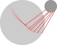
We have a series of radial lines from A to C of length R. I will give points
for 3 values of R, namely 50, 100 and 150 but to do this properly it is best
to calculate many more points (that's what spreadsheets are for).
We have corresponding line segments CD which are orthogonal to the radii AC.
This is the length of the main part of the arm, we will set it to some fixed
value and I'm going to use 150 so the two examples are similar. If we then
draw the line DA for each point D we have a right angle triangle with the
two right sides known, the hypotenuse is found by Pythagoras. For the radii
chosen, the hypotenuses are 158.1, 180.3 and 212.1. The angle ADC will be
ARCSIN (AC / AD) so we have 0.321, 0.588 and 0.785 respectively*. Each
segment CD is part of a longer segment CB where B is the intersection with
the base line. Note that with this geometry the point B is different for
each radius, unlike the Birch geometry where it is fixed.
We now set the pivot point P. Let's make the length of the arm from pivot P
to each point D 60 mm. If the length AP is made to equal the sum of PD and
DC, then the arm will have zero overhang, so we set point P at (-210,0).
This defines a second triangle with three known sides so we can use the
cosine rule <http://en.wikipedia.org/wiki/Law_of_cosines> to calculate the
angles APD which are thus 0.449, 0.923 and 1.463. This in turn allows us to
define point D for any radius. The X coordinate will be -210 - PD*COS APD,
the Y coordinate will be PD sin APD so the three points D are (-155.9,
26.0), (-173.8, 47.8) and (-203.6, 59.6).
In turn this means we can calculate the angle PAD which is simply ARCTAN
(Yd/Xd) for each point D giving -0.165, -0.269 and -0.285 respectively. Each
segment CD is part of a longer segment CB where B is the intersection with
the base line. Note that with this geometry the point B is different for
each radius, unlike the Birch geometry where it is fixed.
We can now calculate the angle ABC which must be equal to ADC + PAD. The
slope of the line BC is the tan of this angle so we have 0.157, 0.330 and
0.546 respectively. Since we have a slope and a point on each line (the
points D) we can calculate the intercept with the base line which will be
the point B by substituting into y = mx +b the same was we did previously,
obtaining intercepts of -321.4, -318.55 and -312.68 respectively.
Although this looks like the geometry is quite different from that of Birch,
it isn't. The difference is that we've put both B and P on the base line
whereas with Birch geometry P is always below the base line. We can show the
equivalence by calculating the equivalent "Birch line" and finding the
intercepts which will fall near the opposite Thales locus. In this case that
locus is at (-315, 2) but I'm not going to clog things up by showing you how
to find this.
The beauty of this geometry is that we do not need to use the Thales locus
so we can completely eliminate the errors in the Birch geometry. We do this
by getting rid of the remaining variable length, which is the length BD.
Instead we assign a new set of points E which fall a defined distance past D
on the line CB. Since we know the equation of the line and the points D, for
a given length DE the points E are defined by Xe = Xd- DE * slope, Ye = Yd -
DE * ( 1 - slope^2). These points will define a track which will constrain
the motion of the segment DC so that the angle DCA is always 90 degrees.
The fun bit is designing the interface between the arm and the track.
You now owe me two beers.
* Angles in radians.
Please note that I'm using the spindle as the origin in these calculations
where I used the point B in the last. This simplifies the maths a bit. If it
causes confusion, the best option is to beg the mods to allow me to edit the
previous post and I'll change the co-ordinate system so they're both the
same.
We have a series of radial lines from A to C of length R. I will give points
for 3 values of R, namely 50, 100 and 150 but to do this properly it is best
to calculate many more points (that's what spreadsheets are for).
We have corresponding line segments CD which are orthogonal to the radii AC.
This is the length of the main part of the arm, we will set it to some fixed
value and I'm going to use 150 so the two examples are similar. If we then
draw the line DA for each point D we have a right angle triangle with the
two right sides known, the hypotenuse is found by Pythagoras. For the radii
chosen, the hypotenuses are 158.1, 180.3 and 212.1. The angle ADC will be
ARCSIN (AC / AD) so we have 0.321, 0.588 and 0.785 respectively*. Each
segment CD is part of a longer segment CB where B is the intersection with
the base line. Note that with this geometry the point B is different for
each radius, unlike the Birch geometry where it is fixed.
We now set the pivot point P. Let's make the length of the arm from pivot P
to each point D 60 mm. If the length AP is made to equal the sum of PD and
DC, then the arm will have zero overhang, so we set point P at (-210,0).
This defines a second triangle with three known sides so we can use the
cosine rule <http://en.wikipedia.org/wiki/Law_of_cosines> to calculate the
angles APD which are thus 0.449, 0.923 and 1.463. This in turn allows us to
define point D for any radius. The X coordinate will be -210 - PD*COS APD,
the Y coordinate will be PD sin APD so the three points D are (-155.9,
26.0), (-173.8, 47.8) and (-203.6, 59.6).
In turn this means we can calculate the angle PAD which is simply ARCTAN
(Yd/Xd) for each point D giving -0.165, -0.269 and -0.285 respectively. Each
segment CD is part of a longer segment CB where B is the intersection with
the base line. Note that with this geometry the point B is different for
each radius, unlike the Birch geometry where it is fixed.
We can now calculate the angle ABC which must be equal to ADC + PAD. The
slope of the line BC is the tan of this angle so we have 0.157, 0.330 and
0.546 respectively. Since we have a slope and a point on each line (the
points D) we can calculate the intercept with the base line which will be
the point B by substituting into y = mx +b the same was we did previously,
obtaining intercepts of -321.4, -318.55 and -312.68 respectively.
Although this looks like the geometry is quite different from that of Birch,
it isn't. The difference is that we've put both B and P on the base line
whereas with Birch geometry P is always below the base line. We can show the
equivalence by calculating the equivalent "Birch line" and finding the
intercepts which will fall near the opposite Thales locus. In this case that
locus is at (-315, 2) but I'm not going to clog things up by showing you how
to find this.
The beauty of this geometry is that we do not need to use the Thales locus
so we can completely eliminate the errors in the Birch geometry. We do this
by getting rid of the remaining variable length, which is the length BD.
Instead we assign a new set of points E which fall a defined distance past D
on the line CB. Since we know the equation of the line and the points D, for
a given length DE the points E are defined by Xe = Xd- DE * slope, Ye = Yd -
DE * ( 1 - slope^2). These points will define a track which will constrain
the motion of the segment DC so that the angle DCA is always 90 degrees.
The fun bit is designing the interface between the arm and the track.
You now owe me two beers.
* Angles in radians.
Last edited by a moderator:
It is rather amazing, that after one hundred years of disc record players history , new purely mechanical arm designs are still coming, and they still are able to come closer and closer to perfection. The last Schroeder design looks like almost final stage, but who knows...
Nice Thread.
In 1970, i was working in the research and department office of Scientelec (A well known French hifi manufacturer at this time).
There were too a famous manufacturer of professional turntables and PU cartridges Clement (He equipped the state French Radio "ORTF").
Clement
He produced a Radial arm turntable:
Platine bras radial
http://www.audiofolia.com/Download/RDS201.pdf
The first, as far as i know, to have a strait free arm on a chariot , measuring the angle error with a light, and moving the arm's charriot with a motor.
Back to my story. I wanted a radial arm for my company too. So, i had offered two patents (around 1970) to my company. The first one was a pure copy of the clement's one, with just the idea that, instead of moving the arm, it was the record plate witch moved under the arm.
The second idea was to fix the arm at the periphery of a rotating plate, and to make-it turn in order to correct the error.
The arm itself is free on the two axes, the error of angle is detected under the main plate by a light and two photo cells. Each time the arm is moved by the grove to the inside, it create an error, the the motor make rotate the A plate until the error is 0.
On my point of view, any system where the head is making an angle is messy, as it create a "centripetal ?" force.
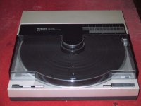
To conclude, i would like to point out the most intelligent radial arm turntable ever:
Technics SL7.
Technics SL-7 Owners Manual, Service Manual, Schematics, Free Download | Vinyl Engine
The arm, his chariot and his motor was in the cover: you do not have to wait for it to be parked before opening the cover. Brilliant. This plate was able to detect the size of the record, and was fully automatic if you like: one button press.
That the one i use.
In 1970, i was working in the research and department office of Scientelec (A well known French hifi manufacturer at this time).
There were too a famous manufacturer of professional turntables and PU cartridges Clement (He equipped the state French Radio "ORTF").
Clement
He produced a Radial arm turntable:
Platine bras radial
http://www.audiofolia.com/Download/RDS201.pdf
The first, as far as i know, to have a strait free arm on a chariot , measuring the angle error with a light, and moving the arm's charriot with a motor.
Back to my story. I wanted a radial arm for my company too. So, i had offered two patents (around 1970) to my company. The first one was a pure copy of the clement's one, with just the idea that, instead of moving the arm, it was the record plate witch moved under the arm.
The second idea was to fix the arm at the periphery of a rotating plate, and to make-it turn in order to correct the error.
The arm itself is free on the two axes, the error of angle is detected under the main plate by a light and two photo cells. Each time the arm is moved by the grove to the inside, it create an error, the the motor make rotate the A plate until the error is 0.
On my point of view, any system where the head is making an angle is messy, as it create a "centripetal ?" force.
To conclude, i would like to point out the most intelligent radial arm turntable ever:
Technics SL7.
Technics SL-7 Owners Manual, Service Manual, Schematics, Free Download | Vinyl Engine
The arm, his chariot and his motor was in the cover: you do not have to wait for it to be parked before opening the cover. Brilliant. This plate was able to detect the size of the record, and was fully automatic if you like: one button press.
That the one i use.
Attachments
Last edited:
Esperado: "The second idea was to fix the arm at the periphery of a rotating plate, and to make it turn-in order to correct the error.
The arm itself is free on the two axes, the error of angle is detected under the main plate by a light and two photo cells. Each time the arm is moved by the grove to the inside, it create an error, the the motor make rotate the A plate until the error is 0."
Conceptually, the rotating plate with point A resembles Birch geometry with point P, except one is motorized and the other mechanical. I'm curious as to how you make all the red lines converge to or close to point B on the Birch design? Or is it even necessary?
An externally hosted image should be here but it was not working when we last tested it.
walterwalter: "It is rather amazing, that after one hundred years of disc record players history, new purely mechanical arm designs are still coming, and they still are able to come closer and closer to perfection. The last Schroeder design looks like almost final stage, but who knows..."
I am amazed that nobody is talking about it. Frank is a modest guy and his design is flying under the radar but people need to talk more about such revolutionary design instead of talking about upgrading their next air-pump!
They only converge ...at infinity ;-)I'm curious as to how you make all the red lines converge to or close to point B on the Birch design? Or is it even necessary?
Conceptually, there is nothing in common. Whatever the distance of the head from the center , there is always a position of the plate A (as you can see on my design) for the Diamond of the head to be on the tangent. You don't have to know where, as the error correction system will turn the A plate in the good direction untill no error (the light hit the center of the record plate).
Exactly like the Technics or the Clement. The arm is totally free on the two horizontal and vertical axes.The difference is that, on the traditional radial arms, the error system can be in the arm itself, looking for good perpendicularity between the arm and his chariot.
Here the error will be measured by 2 cels at the vertical of the record plate axe. If the light hit the Right cell, the motor will turn the A plate clockwise, if it hit the left cell, anticlockwise. When the light is right in the middle (no error), the motor is stopped.
The advantage of this system is just that it is easier and cheaper, on a mechanical point of view to rotate something than to generate a linear movement.
Note that the second parallel arm under the plate will have an advantage, resonance of the arm (with the cell suspension) will not be the same in vertical and horizontal direction.
For me, the Technics was absolutely perfect: you cannot hope something better. Heavy, easy to run, and the size was just 30cm X30cm, the exact size of the 33RPm. More, you where obliged to run the turntable closed, so, no dust. And it was not a so expensive turntable....they still are able to come closer and closer to perfection.
Last edited:
Quote:
Here the error will be measured by 2 cels at the vertical of the record plate axe. If the light hit the Right cell, the motor will turn the A plate clockwise, if it hit the left cell, anticlockwise. When the light is right in the middle (no error), the motor is stopped.
The advantage of this system is just that it is easier and cheaper, on a mechanical point of view to rotate something than to generate a linear movement.
Reply:
Design is elegance itself, among electronically controlled linear trackers.
They only converge ...at infinity ;-)
Conceptually, there is nothing in common.
No that's not true. DDs supposition is correct, the geometry is a variation on the Birch geometry.
If you construct an extension of the arm past the circumference of the circle you will find that these extensions approximately converge at the opposite Thales locus. The servo system basically reduces the error inherent in the Birch geometry. Frank's guidance system serves a similar pupose.
It would be possible to dispense with the servo system entirely and use the convergence of the arm extensions to establish something very close to tangential tracking.
Esperado if you have the exact length of the arm, the radius of the chariot (between pivots) and the distance from the platter spindle to the chariot's centre I will show you how it conforms to Birch geometry. It would be interesting to measure the actual error in the servo system and see how the two compare. What is the distance between the two lights cells?
Last edited:
Thanks for pointing out the geometric relationship. To be honest, I much rather have a mechanical system than a motorized or air-bearing system if I can help it. Perhaps my hatred of air pump is unreasonable but at least it prompted me to start a thread like this.
(Hell, I don't even like air pump for my fish tank! No offense to the air-bearing users--just enjoy the pleasure your product provides you--I just want a different route.)
P.S. Oh Mark, that "99% ape" comment that I accidentally caught was brilliant and it tickled the atheist in me.
(Hell, I don't even like air pump for my fish tank! No offense to the air-bearing users--just enjoy the pleasure your product provides you--I just want a different route.)
P.S. Oh Mark, that "99% ape" comment that I accidentally caught was brilliant and it tickled the atheist in me.
Mark Kelly: And now to Floating B.
Although this looks like the geometry is quite different from that of Birch,
it isn't. The difference is that we've put both B and P on the base line
whereas with Birch geometry P is always below the base line...
The beauty of this geometry is that we do not need to use the Thales locus
so we can completely eliminate the errors in the Birch geometry. We do this
by getting rid of the remaining variable length, which is the length BD.
If B is floating and not at a fixed point, then the arc created by all the C points is no longer a part of a "perfect" circle, right? Or is the perfect circle still there but line angle or something has changed? Again, my terminologies are clumsy at best but I hope you understand my question.
Mark Kelly: "I try to stick to the rule never to discuss religion or US foreign policy on the intertubes. It never ends well."
I understand but it probably cannot be worse than talking about cables or Linn turntables.
Last edited:
Esperado: "The advantage of this system is just that it is easier and cheaper, on a mechanical point of view to rotate something than to generate a linear movement."
I agree mechanically it's simpler to rotate a plate than it is to glide on a track and it's easier to install because of the smaller footprint but it complicates the geometry more than I would like. However, if it's a purely mechanical design then we're really on to something...
If B is floating and not at a fixed point, then the arc created by all the C points is no longer a part of a "perfect" circle, right? Or is the perfect circle still there but line angle or something has changed? Again, my terminologies are clumsy at best but I hope you understand my question.
Your terminology is clear enough, but I'd prefer to call it the curve created by all the "C" points; in geometry an arc is always part of a circle (the everyday use of the term is much looser). Also "perfect circle" is a tautology - it's either a circle or it isn't. It's a bit like being completely pregnant.
Anyway, your main point is correct. If we construct backwards from the tangent lines (CD in my construction above) we end up with a different point B for each point C. This differs from Birch where B is fixed and the lines CD are not tangents (I almost wrote "perfect tangents").
In the real world the differences are very small and in many cases they disappear - as I've said before it's easy to construct a Birch arm with less than 0.1 mm error at any point and I know of no method of aligning a cartridge to that level of accuracy. Similarly constructing backwards from tangency you will often find that the points B lie very close together and the appropriate arm segment for many constructions would pass though each of the points B to within the tolerances of things like bearing clearances.
Just to repost the Birch diagram with the addition of "D" points.
Mark, I owe you more than two beers but I'm not sure you'll be able to do math after that. As a featherweight drinker, I know I can't!
Mark, I owe you more than two beers but I'm not sure you'll be able to do math after that. As a featherweight drinker, I know I can't!
An externally hosted image should be here but it was not working when we last tested it.
An externally hosted image should be here but it was not working when we last tested it.
Mark Kelly: "A better statement of your second sentence might then be "as the length of the segment CD decreases, the length of the segment PC increases and the pivot point P moves closer to the middle point of the Thales semicircle. When CD becomes zero the Birch design becomes a Thales arm"
Can I say if point P is located exactly at "Midpoint" of A & B, and point D becomes or on point C, then the Birch design becomes a Thales arm?
I wish the tonearm can generate this kind of ABC.

Referring to post #236:
Two things that might need changing:
The magnetic system is referred to as a guide rail so it's almost certainly not a single point.
If you extend each of the lines CD past the points D by some fixed amount, creating a third set of points which I've called E in one post above, you create a curve which can be used to compensate for the errors in the Birch geometry. To complicate matters further, there is no reason that the line segments CD and DE need to be colinear, they could just as easily be at some other angle. Changing the angle between the segments changes the shape of the curve produced at the points E. If you don't want to introduce anothe pivot the angle needs to be constant.
To be true, i don't know. I was 24 years old at this time, and don't knew this " Birch " study (what is the date of publication ?). I still have to read previous messages here about it, if i get some time for it.No that's not true. DDs supposition is correct, the geometry is a variation on the Birch geometry.
As there is no solution with a strait arm of a fixed size articulated on a fixed pivot to be tangential at more than on point, my idea was just to move the pivot and don't care about the geometry. The electronic error correction system has only to deal with a dimension: "too short", "too long".
Maybe the geometry converge somewhere, may-be not. It is a virtual thing, no real concern. The purpose was to have a reasonably sized turntable (we where building mass products) witch do not involve expensive mechanical pieces.
About error, it depends of the way you build-it. (how precise is the measurement, how fast is your motor). Exactly like a linear tracking on a chariot. In real world, keeping this angle error little enough at the end of the record (where it produce the ore distortion) for you cannot measure or hear-it is easy. Remember that, on the groving machine, the speed of the chariot is musical level dependent, not constant, so angle's errors will ever exists.
The only difference between linear tracking and my idea is so easy to build that you can DIY. (Harduino ?)
Let resume the important points, omho.
First we can eliminate all systems with bent arms , as angles introduce centripetal force I.E. tracking distortion on the head.
Second, motorized tracking will be easier and less expensive than pure mechanical with the frictions problems or other parasitic forces it involves.
The arm has to be free on his 2 axes. Care has to be taken for friction and specially the torsion forces of the wires (not easy)
The shorter/ lighter the arm the better, for inertia and resonance problems concerning the head. With vertical angle inconvenience if the record is not flat.
I had never found something more intelligent, simple, and well produced than the Technics SL7. This turntable resume the state of the art, for me the best turntable ever. Direct drive plate, with no flutter or rumble. Non resonant rectangular profile short arm ( in the cover, so easy, so clever), Automatic detection of the size of the record (speed and initial position of the head, with a brilliant simple detection light detection system): you open the cover, put the record in, and press a button to play. Open the cover any time to stop, or wait the turntable to do-it itself. The turntable is very heavy, the smallest you can find, with a good suspension, and no resonnances nowhere. There is a dumping mass witch press the record on the top to eliminate his vibrations. I have added an anti-static brush moved by the chariot to eliminate the durst while playing, and changed the 'plate cover ?' material for an anti static silicon heavy one. Well, only one inconvenience: no way to scratch with it ;-)
Last edited:
- Home
- Source & Line
- Analogue Source
- Angling for 90° - tangential pivot tonearms