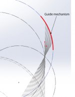
I send you what i was doing. If you enlarge the rear zone you may see that the circle seem to performe not better than the line.
The red elongation segments are cut and pasted geometrically from the two circles by the program, so i think they are exact (unlike dimensions, that are rounded - you say so?). so the errors seen are real.
do you think that the string gadget can be simulated? maybe is better than i thought, a sort of pantograph reproducing the curve at the headshell level-
good night - carlo
Attachments
Yes I can simulate for you.
I would need maximum extended length and the minimum as well as the precise locations on your curve where that will happen. Assuming lead in & lead out. What are your thoughts on the easy of use of such a long mechanism on current plinths? Would this be a pod mounted solution?
I would need maximum extended length and the minimum as well as the precise locations on your curve where that will happen. Assuming lead in & lead out. What are your thoughts on the easy of use of such a long mechanism on current plinths? Would this be a pod mounted solution?
Do not worry 2wice, thanks. I was just asking if it's feasible. For the build, my good old Kern compass (far more precise than me) and the slide rule may be enough.
Plinth: no separate arm base, for my taste! No decoupling! i'm building a turnatable from years, but never made a spindle sufficiently good (far more difficult to keep it silent than making a tonearm). So i'll test on my LUx, with separate arm base. But a shorter Thales (9" vs 12") means more elongation, longer rear section, larger angle, bigger problems, imho. What will be the guiding mechanism? aligned as suggested by Ray?
You're right Super10018, I've said. But that way is hard to do something different or better or than Schroeder LT. In his sketch the curve is a n arc but from his words may be argued that he also slightly modified the magnetic curve to correct the residual skating.
However, for diyers the challenge is not only to design, but also to realize difficult things with their skill and tools. Even making ships in bottles: do you know something more useless?
carlo
Attachments
Last edited:
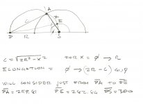
In case anyone would like to draw this for themselves.
I’ve calculated the overhung/underhung and tangency errors of following the arc of the top circle compared to the calculated points on tangency curve.
In the top 2/3 of the curve the biggest error is -170µm underhung for 80µ° tangency error.
In the bottom 1/3 the biggest error is +180µm overhung for 130µ° tangency error. Any mechanical device will exceed these tolerances so I think following the arc is probably safe.
Even making ships in bottles: do you know something more useless?
You're a hoot! Always came up with great lines, off tangent!

Hi 2wice,
Can I just check your figures. When you say a -130u° error do you mean -0.13° or -0.00013°. My quick check would indicate the former. The u=micro which would indicate the latter. 0.00013° is so close to zero as to be not worth mentioning and is definitely not audible. Even if it is 0.13° it is still very small and probably inaudible in itself.
Very nice work.
Niffy
Ignore me I've just spotted the angle in the bottom box. 89.87° = -0.13°. Still small enough to ignore. A slightly eccentric record will give as much lateral tracking error. And I can't hear it on those.
Last edited:


Hi all.
If the curve made by the rear of the arm is so close to being an arc then the simplest way of getting the rear of the arm to follow that arc is by using a simple linkage connected between the centre of the circle the arc is a segment of and the rear of the arm. The quality of bearings would have to be high as any play would have a negative effect on tangentcy, (have I just made up a word?). If you want absolutely accurate tracking then a guide rail with micron accuracy would be needed, way beyond my capabilities to make.
Using pin bearings, as used in clocks and compasses, would give minimal friction and play.

Niffy
If the curve made by the rear of the arm is so close to being an arc then the simplest way of getting the rear of the arm to follow that arc is by using a simple linkage connected between the centre of the circle the arc is a segment of and the rear of the arm. The quality of bearings would have to be high as any play would have a negative effect on tangentcy, (have I just made up a word?). If you want absolutely accurate tracking then a guide rail with micron accuracy would be needed, way beyond my capabilities to make.
Using pin bearings, as used in clocks and compasses, would give minimal friction and play.
Niffy
What stops that linkage from just being a string? It's only job is keeping the rear from going over the curve.
Eccentricity can then be handled by slack in the string. There's no friction or pulley involved and inwards travel keeps the tension.
This will only work if the sliding mechanism has no lateral play. Perfect job for a swiveling air bearing. But passive is the grail and goal for me.
Eccentricity can then be handled by slack in the string. There's no friction or pulley involved and inwards travel keeps the tension.
This will only work if the sliding mechanism has no lateral play. Perfect job for a swiveling air bearing. But passive is the grail and goal for me.
What stops that linkage from just being a string? It's only job is keeping the rear from going over the curve.
Eccentricity can then be handled by slack in the string. There's no friction or pulley involved and inwards travel keeps the tension.
I don't think the string will work in this case. The forward travel of the arm need a pulling force to stop the overshoot. But the string tied point is in front of the tail. And a string cannot push either. A water skier can't be pulled by a jetski if he's in front of it. The string will work in a Birch arrangement if the arc is in front of the arm's pivo point, hence my initial design in the earlier post.
I still prefer a V-grooved bearing attached to arm's tail riding on a curved blade as a track.
Last edited:
Hi all. Everyone seems to understand everything about 2wice smart analysis and sees many feasible solutions at hand. i'm instead rather confused.
Dd clarified that:
"Stylus to arm end is fixed length but stylus to pivot is NOT fixed length obviously. It's still going through the "elongation" process."
So it would seem like an extensible Thales, but how? I can imagine just two possible solutions
1 - the arm stretches, but the pivot does not move
2 - the arm does not stretch, but the pivot moves
(attachment)
1 - of this I can talk (still not in practice) because this is what my Syrinx tries to do.
Here the control point is the center of the blue circle. Geometrically it is perfect, but the direction is unfavorable (almost orthogonal) either to push (like in mine) or to pull (stylus drag control) without creating moments that hinder the linear extension of the arm. Not to mention alignments (skating).
2 - of this i can't, too little knowledge: i can only say that for me it's no more a Thales, maybe nearer to LT or tricycle
ciao carlo
Attachments
I still prefer a V-grooved bearing attached to arm's tail riding on a curved blade as a track.
Hi DD.
IMO one of the most important aspects of the guiding mechanism has to be bearing friction. Any resistance to movement will result in the cantilever being deflected from the tangent.
With a bearing running on a curved rail the bearing will have to make at least one full revolution. With the linkage design the bearings at either end will each have to rotate through only about 30°. The loading on the bearings will be about the same in each design. As the single bearing in the rail design has to rotate about 6 times the total amount of the two bearings in the linkage design the bearing friction will also be about 6 times as high. On top of this you have to add the rolling resistance between the bearing and rail. (The bearing on a rail is similar to that of a mechanical linear tracking tonearm just turned on its side. Mechanical linear tonearms all have high lateral friction compared to pivoted arms regardless of bearing quality.)
The advantage of the rail design is that you can fine tune the curve for zero geometric tracking error. However the increased friction will probably outweigh this.
Niffy
1 - the arm stretches, but the pivot does not move
2 - the arm does not stretch, but the pivot moves
You're making it more complicated than you think. They are the same thing. The stylus to the pivot point (P) distance is ALWAYS changing, hence the elongation. The stylus to the tail is a fixed distance. It's all about the relationship with the almighty P. How you make this sliding around is up to you. As long as the arm lines converge into a single point, you are always using the Thales geometry as a reference. 2wice's drawing is just a variation of the Birch method, except he's found an arc BEHIND the pivot point (P). Birch geometry is not 100% tangent at all times, only 3 points are perfectly tangent, with underhang and underhang just like a pivot arm, but the error is in microns! By having guiding geometry in arcs makes building easier because you can use pivot linkages or curved rails with less dramatic bend.
Your two drawings below are already full of arcs and possibilities. How you make the guiding mechanism is up to your inventiveness, which is tremendous.

IMO one of the most important aspects of the guiding mechanism has to be bearing friction.
Niffy, you're probably right about the difference in bearing friction. However, the way I imagined it is that the tail V-groove bearing exerts no mass or pressure on the rail since it moves only horizontally it's not carrying the mass of the carriage. You're right that on the horizontal plane there's the resistance in push and pull. Wanting the rail design is partly aesthetic because it's compact without extra extension rods sticking all over the place. I have to think more about this.
This is the way I'm going to shoot at it.
1 rear stub carriage about 105mm long that has a horizontal knife bearing at the back that rides a groove in the front face, with magnetic preload to keep it in the groove.
The bottom 6/10th of the carriage is a halbach array on the bottom and sides.
That passes through a halbach tunnel, the center of which forms the pivot.
I know Earnshaw says "Nah gtfo" but the rear loaded knife contact is the required stability point.
Fixed to the carriage that passes through the halbach tunnel is the armwand and counterweight.
Vertical pivot only transverses a total of 52.29mm with the starting point above the horizontal pivot.
So it's a split plane rear carriage with vertical pivot nearly at the end of it(97.39mm). Stylus to vertical pivot = 152.61mm.
So the stylus to rear knife bearing does not change but vertical pivot travels.
I'm hoping that the obtuse angle between the carriage and curve, and the preload will allow the arm to go backwards.
- Home
- Source & Line
- Analogue Source
- Angling for 90° - tangential pivot tonearms