Planning to mod my Keith Monks uni-pivot re-designing a straight head shell, mounting the pedestal on a computer servo driven linear platform.
Welcome Slo-Blow! Glad you're enjoying the thread. I was thinking about servo platform the other day. Since pivot arm is a mature design, why not use it to its advantage and mount it on a platform that allows it to correct for tangency. This has been mentioned by member Conrad Hoffman before. I think member Straightracker's motorized version of his design is also similar. I know this maybe off topic since I want to focus more on mechanical designs instead of servo but sometimes, (pun intended) go off tangent! 😀
Okay, instead of a platform that glides across the radius of the record (at least 4 inches, from lead in groove to the record label), like typical linear trackers like Goldmund, why not use the Thales geometry and only have to move no more than 2 inches that allows a much simpler design and space saving platform. I think it's perfect for a 12 inch pivot arms (straighten the headshell, of course) so you can have the platform outside of the turntable plinth. Think of it as an tonearm island that servo glides only an inch.... or the base portion of Scrhoeder's LT arm but motorized.
Another approach is to use something similar to what member Esperado mentioned in post#225, that is, to a rotational platform that approximate the Birch geometry. It probably has minuscule skating force compare to traditional pivot arm with offset angle.
An externally hosted image should be here but it was not working when we last tested it.
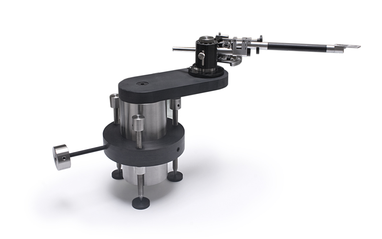
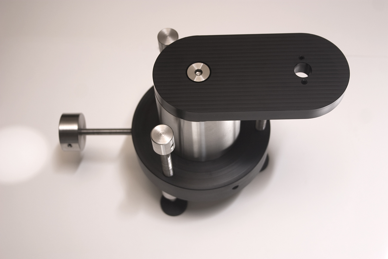
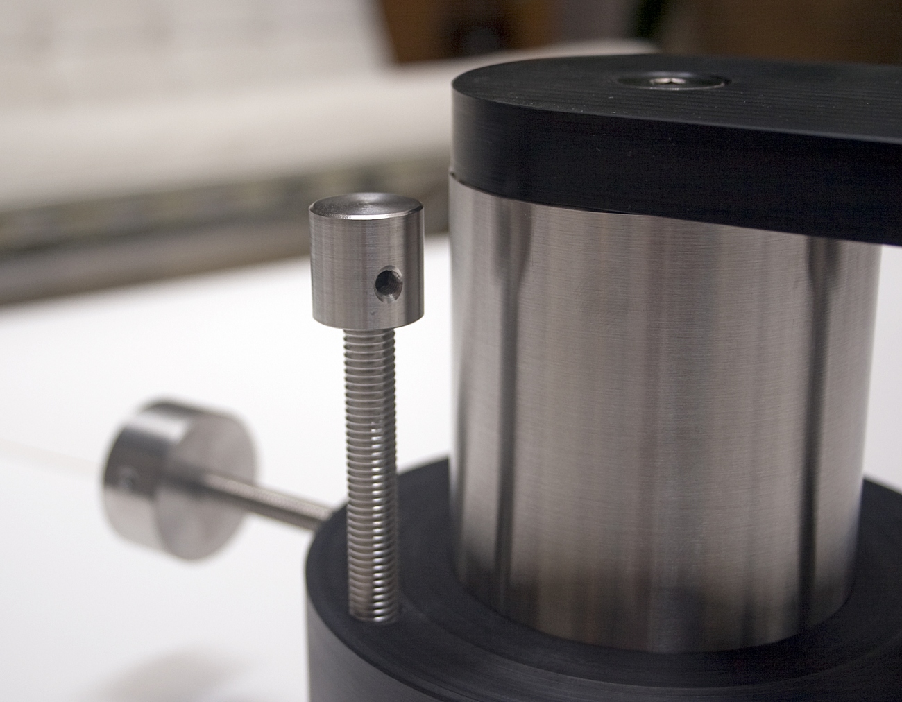
I was looking at an after market accessory and thought of its application and it can be modified to suit our purpose. Think of it as a servo motorized rotating platform to correct for tangential tracking. Again, it allows for a quasi-Birch geometry.
All wacky ideas are welcome in this thread. 😀
.
Speak of the devil, someone came up with what I just contemplated already in another forum thread!
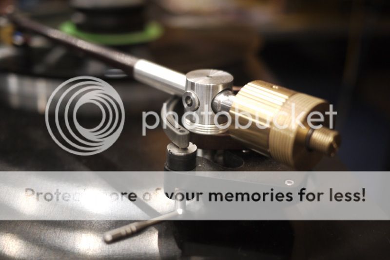
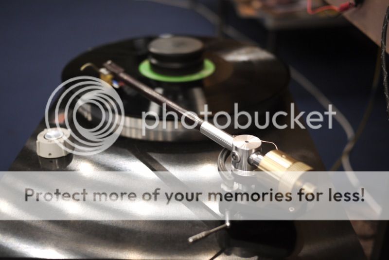
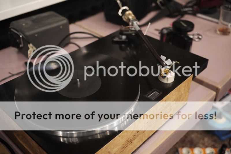
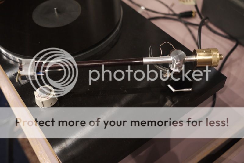
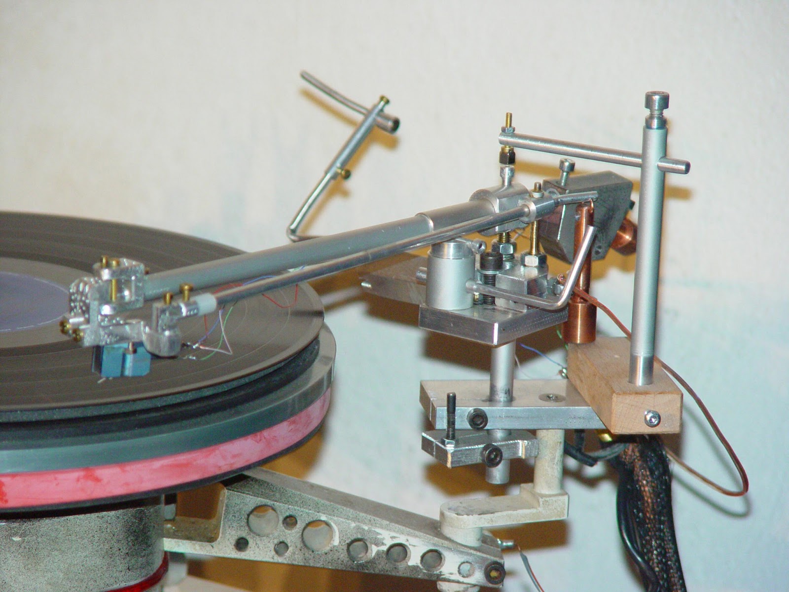
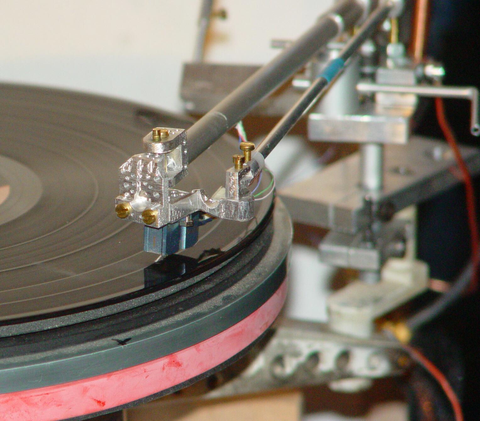
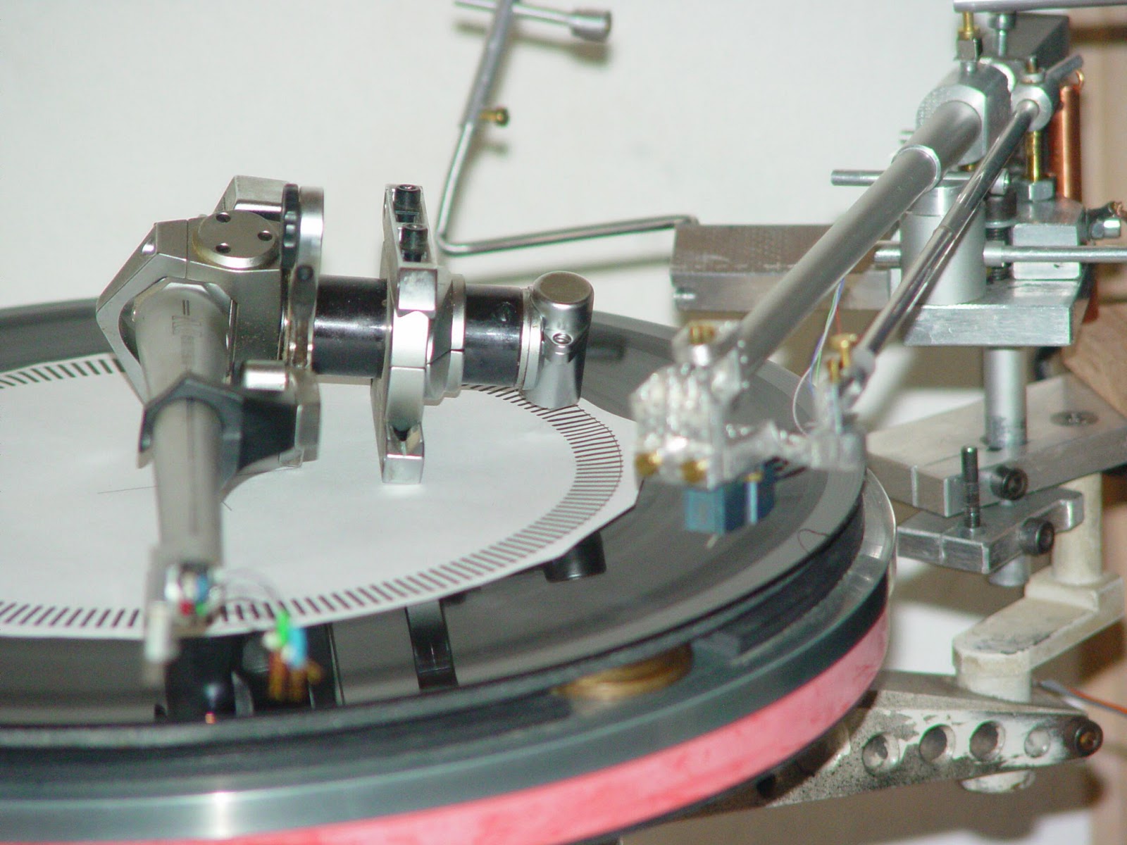
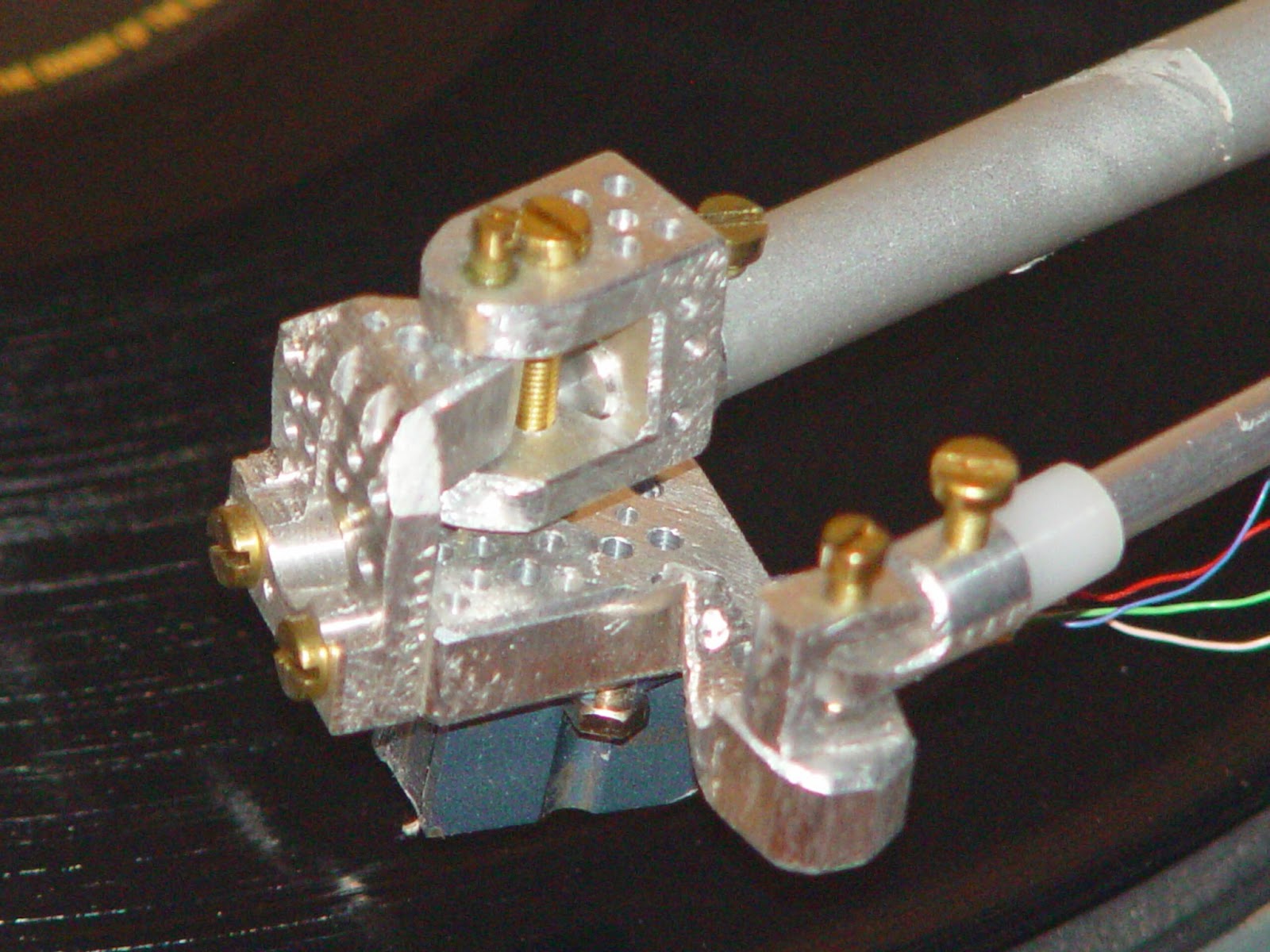
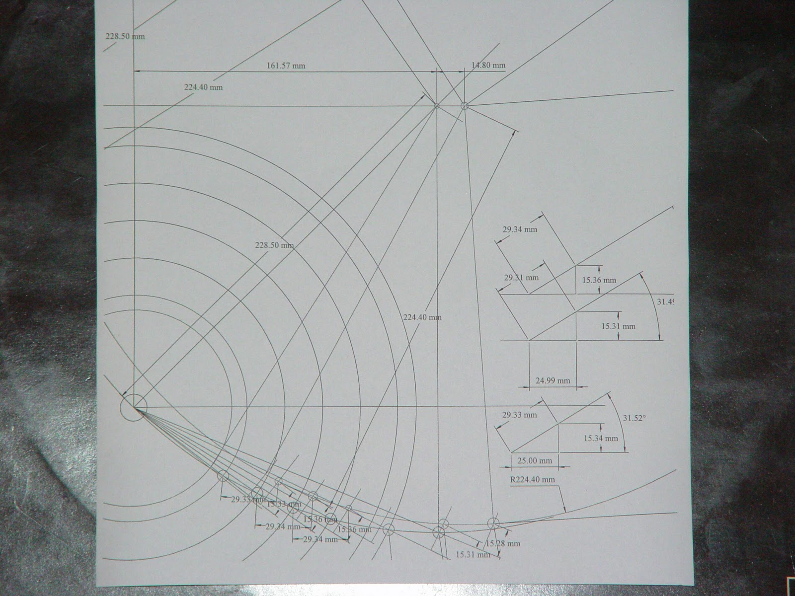
"The arm pivot travels towards the spindle as the record plays, fed out by a clock, and maintains the stylus in tangent. 80mm travel in 20mins is the assumption, based on the average of 30 records I measured at random. Standard Deviation was 13.6mm. ( ie 68% of records were within +/- 13.6mm over 20mins). Travel of the arm pivot vs travel of the stylus across the record is non linear, but is corrected by a cam on the clock tape feed. You can sight along the face of the cartridge (Denon 103 with Midas /Touch - thanks David) to the spindle and check on how well it is doing - uncanny to see it following the maths smiling. The arm is a modified Grace 707 with a Jarrah extension, and a pressed in brass counter weight. And amazingly it sounds wonderful."
An externally hosted image should be here but it was not working when we last tested it.
An externally hosted image should be here but it was not working when we last tested it.
An externally hosted image should be here but it was not working when we last tested it.
An externally hosted image should be here but it was not working when we last tested it.

tetragonal tonearm
This thread has been quiet. Thanks to member peril who alerted me in another thread to this DIY tonearm that, I think, would fit into the topic of this thread. I hope peril doesn't mind.
This is from a website written in German.
This looks like another variation of tetragon solution such as the Garrard Zero 100 or Burne-Jones or the Thales Simplicity.
The interesting touch is that the pivot at the base is a unipivot design. In fact it's made of TWO unipivot points which I proposed in earlier post about the Van Eps tonearm.
Last edited:
Hello, directdriver
I posted some comments on your thread a year or so ago, and have been actively trying to bring an updated version of my patented arm (4,497,053) to the manufacturing stage. You, and a few others, have a pretty good idea of what arm techniques are all about, for which I am grateful.
My problem has always been that I need a machine shop. When I lived and worked in Silicon Valley, we had plenty. 25 years later, most have closed, retired or off-shored the work to Asia. They don't have that problem in Germany or Switzerland!
The second problem follows from the first. The shops I have talked to see me as their next victim. They want excessive set-up fees, and per-part costs that are recoverable when I am over 100 years old. And I have no way of judging their quality of work.
One has to be an idiot to think of making arms for a living, and I have no illusions, there. I would like to make some money, as Social Security is a pittance and the stock market is not kind. If you, or someone you know (Ralf?) can help here, please let me know.
FYI, the arm is as in my patent (a single head-shell pulley) plus anti-skate and height adjust. No arm-lift at the present. Lateral tracking error is effectively zero, skating-force correction is exact, and moving mass is extremely low (a few grams) allowing the very-high compliance pickups of yore to really shine.
A question for you: should the arm wires terminate in RCA jacks, or in a cable with plugs? The former wastes no money on a cable the user won't be using, but then the arm isn't "ready-to-use."
There are close to 60 parts in the arm, so I need to watch costs. Most parts are not economical until you buy a thousand, or so. To ante-up for this game can be an exercise in masochism.
What are your thoughts?
Andy Wolff
23873 Flora Parke Blvd
Fernandina Beach, FL 32034
(561) 322-8005
awolff761@yahoo.com
Speak of the devil, someone came up with what I just contemplated already in another forum thread!
An externally hosted image should be here but it was not working when we last tested it.
An externally hosted image should be here but it was not working when we last tested it.
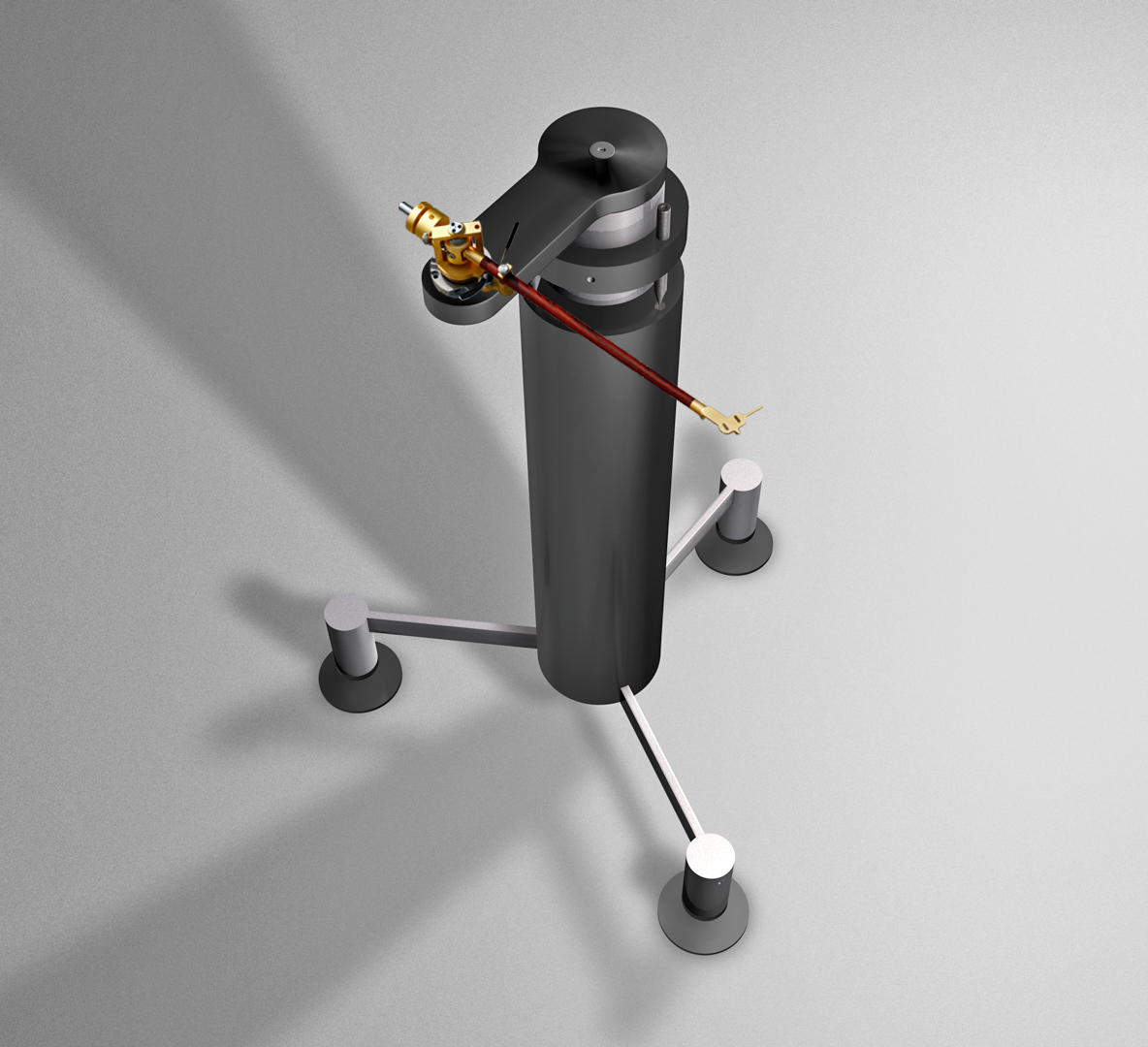
Awwww, my thunder has been stolen! I think this is the most elegant solution. This design separates the function of tracking from the function of traversing (so to speak). One is extremely consistent, and the other is extremely inconsistent.
Interesting geometry though. My go would have been to stick to a radial tracking path.
I like the rotating base idea even better!
Bravo!
My problem has always been that I need a machine shop.
I feel your pain. I have no access to good and knowledgeable machine shop either. A friend has been getting into machining by himself but nowadays he's more into refurbishing machining tools than actually building things. Sigh...
One has to be an idiot to think of making arms for a living, and I have no illusions, there.
Well, Mr. Frank Schroeder is one exception. 🙂
A question for you: should the arm wires terminate in RCA jacks, or in a cable with plugs? The former wastes no money on a cable the user won't be using, but then the arm isn't "ready-to-use."
I would go for RCA. Judging by the success of the VPI tonearms, no one seems to be complaining about using their own RCA cables.
Thanks for chiming in and feel free to share whatever you can to this thread. You're more than welcome to contribute to this great cause. 🙂
Good luck with your project!
Thanks, dd.
I thought of Mr. Schroeder when I wrote that line. I have no knowledge of him other than what I read in these threads. He seems to be a very creative consultant/designer rather than a primary manufacturer. He also may have a "day job," i.e. an alternate main source of income, since at least one of his (patented?) designs is emerging slowly, making the rounds at hi-fi shows.
I also thought of Ralf Dieckmann (aka "Straight Tracker"), who has poured years of development into his arm, been featured in a prominent engineering journal, learned machining, changed his arm from servo-control to something else, etc, and still no commercial product.
I met Adam Rosenberg when he patented his LOCI tonearm in the early 1980s (he was a Stanford undergrad at the time). His was the first VTA-adjust arm, but he sold only 60 of them! (aside: neither he nor I are mentioned in the "comprehensive" arm patent database mentioned elsewhere in your thread [http://www.resfreq.com/phonomusings/phonopatents.html].)
Every arm design I have seen (except my own, of course) improves on one or more aspects of the arm problem but not all of them. We each have our own "priority tree" on this or that improvement's importance. Many arms are simply standard designs with aspirations of being used in the current wave of expensive (and often beautiful) furniture, while others are truly intended for improved operation (as all of us designers fervently believe!). It is fascinating to watch the Thales arms evolve, and one can only admire the intelligence, effort and money expended in their design, development and production.
Without such resources, we are glorified hobbyists with dreams of success. My baby has been on life-support since it was born in 1982. I worked with people like Roger Anderson and James Kogen at Shure (both very supportive) but I produced nothing. In the mid-80s, other life problems took me over, and when I emerged a few years ago, lo and behold, vinyl is still with us! I mean to take advantage of the second chance.
Last edited:
Hi DD,
I have some questions about the driven-platform tonearm many contributors seem to favor. If the pickup is not offset from the arm, the benefit is no side-thrust (aka bias, skating force). The arm mount will be clock- or servo-driven to maintain tangency between the cantilever and groove. This sounds familiar.
The big problem with the SLT is its need to move all that mass (pickup, arm, mount & counterweight). The frictionless designs don’t work well, requiring high-compliance pickups to follow a non-tangential spiral and low-compliance pickups to avoid damage to themselves and the groove. The pickups in feedback-controlled versions do their deviate, correct, deviate, correct, deviate tango continually with some additional baddies, and so forth.
The driven-mount proposal (as I understand it) will have the same problem. The feedback loop will be necessarily slow and can’t be speeded up because it must accommodate eccentric records, variable-groove cutting and warps. It will continually lose perfect tracking and side-thrust immunity.
The problem is that, in the record cutting process, the lathe is driven to the desired location. The electronics preview the sound and control groove spacing accordingly.
In playback, there are no preview abilities. Nevertheless, a lightweight pivoting arm can follow all the pathway squiggles without difficulty. This bears repeating: the groove is telling the arm, via the cantilever, where to go. It is virtually instantaneous.
In the above SLT, the groove is telling a reluctant pickup to move its cantilever out-of-tangency and haul mass (sorry!). In the MPT (Moving Platform Tonearm), the arm is being driven to an expected location with no feedback whatsoever that it is correct. NB: the tighter the servo window, the worse the complications can get.
Granted, nothing is absolute and errors may be “small enough.” What (else) am I missing?
To: Andy Wolff awolff761
Never give up. The world can use another tonearm maker. Tonearms are not
mass produced are they? Pete Riggle Audio Engineering is a one man shop.
James Grant of Analog Instruments Limited is a one man shop. Pete and James
make reasonable price tonearms. Here is hoping you can do the same. I know you can.
awolff761, I wish you luck in your endeavor. I believe you have to create a demand for your tonearm. If your tonearm can compete or out compete others
than you got a winner. First thing when you complete your tonearm have it reviewed by somebody competent and submit review to diyAudio, Audiocircle,
Audio Asylum, Audiogon, Lenco Heaven, Vinyl Engine, Audiokarma and others.
Something to think about. PS. What about making a conventional tonearm?
than you got a winner. First thing when you complete your tonearm have it reviewed by somebody competent and submit review to diyAudio, Audiocircle,
Audio Asylum, Audiogon, Lenco Heaven, Vinyl Engine, Audiokarma and others.
Something to think about. PS. What about making a conventional tonearm?
Hi audiostar,
By "conventional" I assume you mean what I call a PFT (Pivoting Fixed-offset Tonearm).
I have written a 35-page plus booklet about tonearms, their history, patents taken out since the beginning (1896), journal references and popular articles, etc. I came to the conclusion that none of them did what my final design does.
The idea of picking one or another as a product and hyping it as unique or cheaper, etc. was not my focus. What was in my mind was to recognize that no pickup maker could properly evaluate his product if it was not held in the proper orientation and contributed nothing negative in use over the whole disc surface.
Early on, I communicated with AR and Dynavector and found some interest, but the former was just discontinuing their turntable and the latter decided to stay with their proprietary design. AR took some time with their decision and sent me a free turntable as a "consolation prize:" a very classy company.
One can't please everyone, so I have continued to finish the latest version in the hope that there are enough buyers for a better arm. As my previous posts indicate, nothing is perfect. For example, in deciding against SLTs and PFTs, I came to the place all designers do, i.e. wishing there was no skating force. Designs that move the arm as a whole have problems (see previous post) but even the AHT can't compensate perfectly despite its predictable and simple path (which a PFT does not have). Making it adjustable solves some of the problems, but not all.
The compact disc is a superior recording medium and has spot-on timing, but its playback is another story that I'll tell at some point (it involves convolution integrals and interpolating d-to-a converters, for starters).
The big reason, though, is that the billions of vinyl discs out there represent a treasury of music played by either contemporaneous performers or those who were at least immersed in the genres. These cannot be properly archived with current playback components. I have a Brahms Concerto #1 on the original London disc and the CD "reissue." Anytime someone thinks these reissues capture the whole of the original, I play these for him.
I apologize for being prolix, but a simple answer like "I didn't want to make yet another conventional arm" just doesn't work for me. Again, thanks for your kind words and encouragement.
Hi awolff761,
Multi task: the ability to chew gum and run at the same time and come in first.
Plan A: make awolff761 unconventional tonearm a reality and for sale.
Plan B: make awolff761 conventional tonearms for sale. You are smart and you
discover that you can make good or make that very good tonearms.
Wow, a 35 page + essay about tonearms! Please tell me that you
still have this. We the members of diyAudio would like to read your 35 pages + essay on tonearms.
Hi, audiostar
The 35-pager may eventually be available, but the sweat equity is quite large, i.e. $$$$ and some will be used in a white paper (or several) and some will be in the owner's manual.
Thanks for showing me the arms offered by Pete and James. In contrast, mine looks, uh, less good. So far.
As I wrote to Direct Driver, I am still looking for a reasonably-priced machine shop. My arm works just fine using aluminum, epoxy-glass and ABS (all of which I can handle, sort of), but the bar is now quite high in the aesthetics department. Not my strong suit.
I know that members of this thread (and some of the others that you mentioned) can do machining, but I have no idea how to get in touch, etc. I may have to come out with a Mark I version and follow up with a Mark II that is more elegant.
Last edited:
Hi awolff761,
The journey of a thousand miles begins with the first step. Where have you been the last 7 Years? You need your own thread to talk about your tonearm.
Start a thread on diyAudio. You need exposure, an important thing for a would be capitalist. You need to post, post, and post. You need to post on the audio
forums I have mentioned. That will establish your credibility. You can comment
on all things Hi Fi. Talk to your engineering friends about helping you to develop
your tonearm. Network, believe, prayers and the universe will make it happen
for you. When you get the help you need you will be on your way. diyAudio is
about making your dreams come true.
awof761,
If there is a college/community college in your area, you might check to see if they offer design courses - architecture, industrial, art. Students in those fields need projects and if you could find a student who was simpatico with your idea, you might get anything from CAD renderings to a working model.
I tinker with tonearm design and if it weren't for ABS, aluminum tubing, and blue masking tape, nothing would get built.
Best of luck with your project.
- Home
- Source & Line
- Analogue Source
- Angling for 90° - tangential pivot tonearms