Here are some photos of my unipivot tonearm made from a carbon fiber (boron graphite) golf club shaft. It's still in process, I don't have the clips (making those) and the Nextgen RCA jacks.
Attachments
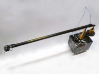
Thanks, Jim. I had purchased eight different carbon composite golf clubs from Goodwill ($3 each - less than half the price of one 4 foot piece from McMaster-Carr) that I chopped apart and then picked the lightest/deadest piece for this project. The length is 16" (approx.) and it required 180gr counterweight. The last straight 10" tonearm I built needed a 145gr counterweight so I feel that this wasn't much of an increase compared to the length. It is also filled with foam and I could have saved weight by using something other than brass for the headshell.
OH! The headshell is brass?? I am planing to use a piece of plain woven carbon sheet bonded (epoxied) to the end of the arm tube. If I might suggest: Aluminum is light and generally dead, particularly in the lower grades (5000 and under). the (common) 6061 is strong, and can be 'ringy'. Magnesium would be better still, but it is hard to get and no shop wants to machine it...
In my case, I need a 15 degree offset, so I will mill the end of the tube top portion at 15 degrees and bond the flat (~rectangular maybe integrate the lift as well) piece on (after milling mount slots). Just trying to determine how exactly I want the stylus with regard to the centerline of the arm tube and/or arm pivot. I am using a cross axle (similar to Rega arm) and can raise or lower the pivot relative to the arm tube etc. Making it all from scratch gives me freedom; the problem is I am not an expert , so it takes a long time to figure out where I want stuff to be!
In my case, I need a 15 degree offset, so I will mill the end of the tube top portion at 15 degrees and bond the flat (~rectangular maybe integrate the lift as well) piece on (after milling mount slots). Just trying to determine how exactly I want the stylus with regard to the centerline of the arm tube and/or arm pivot. I am using a cross axle (similar to Rega arm) and can raise or lower the pivot relative to the arm tube etc. Making it all from scratch gives me freedom; the problem is I am not an expert
, so it takes a long time to figure out where I want stuff to be!What is the pivot made out of? the cup? and how did you attach the cup to the shaft?
Izhakkatz-
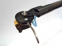
The pivot is steel (end of an upside down plumb bob) ground and polished to a fine point (with a milled-in cup ring so silicone won't creep down the side.), The vee bearing is bronze and balances just past CG, and that is force fit and glued with plastic steel.
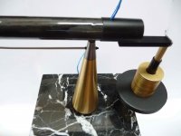
@Jim- I would love to have machining equipment at my disposal but alas; I don't. Aluminum or magnesium would have been my first choice. I wanted a stronger mount that I could make at my jeweler's bench, because with my other arms I've made I've just cut a flat spot in the tubing to screw the headshell to. My wood arms had a similar mounting scheme. The brass mount in this case is pretty light. It is damped by the deadening paint and the cartridge is mounted to a Dymond wood and titanium headshell. I was looking for a more finished appearance on this arm, hence using brass that's silver soldered and hand tooled.
Sounds good! Best of luck with it!
I am still collecting parts for my project...
Hammering out the details on my power supply too...
I have a piece of straight carbon tube on the way (it was cheap) so we'll see if that has enough stiffness at length.
Have to order the motor today!
I am still collecting parts for my project...
Hammering out the details on my power supply too...
I have a piece of straight carbon tube on the way (it was cheap) so we'll see if that has enough stiffness at length.
Have to order the motor today!
Which brings me to this question:
When I mount my tube to the yoke, should the center of rotation (of the cross axle) be in line with the center of the tube (both in the same horizontal plane), in line with the center of the stylus (i.e. mount the tube high relitive to the axle), or someplace else? Does it matter?
Second, since I have complete control over everything, would there be any advantage at all to changing the 'accepted standard' of 21 degrees offset for the yoke bearings in relation to the arm tube? Since that is for 9-12" effective lengths, should I change it (more or less- I have no idea) from the 21 degrees?
If it matters, I have a 14.2" effective length and a 15 degree offset.
I think I may start a new thread...
...And what's a good pivot bearing? I have ABEC 6 ceramic bearings for the yoke; however I need something for the base pivot. What is typical? Should I get another (larger) bearing for the pivot? A tapered roller bearing is the 'right' style for that use; however the frictional load may be too great...
Help!
Help!
I don't know how much it matters. Different cartridges have differing heights, so if it is 'perfect' for one, it will be bad for another...
Rega have it in the same plane (axle and arm) and that's a pretty nice arm, so I'm leaning that way.
The counterweight will most certainly be set low (~in line with the stylus), and close to the yoke.
I will probably stick with 21 degrees, as if it doesn't change for 9-12 inches, it probably won't change for 14.2 inches.
Plus, the more I change, the more reasons for it not to work!
Magnesium would be better still, but it is hard to get and no shop !
Very inspiring project. My father once gave me a 3' bar of magnesium from his lab and for "laughs" I lit one end with a blowtorch. I was then left with the task of putting it out.
@ Scott- Magnesium is scary. A long time ago I worked as a model maker- making belt buckle originals from magnesium (recreating big elk, guys fishing and Mack Trucks. WTF?). We had a grinding machine that I ground the etched magnesium plates on, and even though there was a sign that said that the grinding machine was for magnesium only- "no steel grinding - fire hazard". One day one of the doofus's that worked there ground the tip of a screwdriver and started a fire that we tried to extinguish the fire extinguishers to no avail. The fire department was called and the entire bench in that corner of the shop went up in flames.
Clean all magnesium scraps and especially powders and granules up. Unless you like fireworks. I used to take small scraps home and light them in my parents back yard. One little .5" X 1" piece would light up the entire backyard.
Clean all magnesium scraps and especially powders and granules up. Unless you like fireworks. I used to take small scraps home and light them in my parents back yard. One little .5" X 1" piece would light up the entire backyard.
Hi,
That looks good.
What is the wall thickness of the tube and what is the weight of the arm with and without the end fittings.
One thing comes to mind, and you may have already thought of it yourself, would it be beneficial to incorporate a vibration damper in the balance weight assembly?
Just a thought.
Regards,
Rod
- Status
- This old topic is closed. If you want to reopen this topic, contact a moderator using the "Report Post" button.
- Home
- Source & Line
- Analogue Source
- DIY Golf Club Unipivot Tonearm