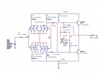
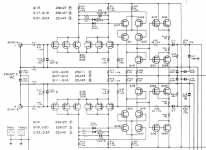
I have been simulating an MC pre-preamp which has a slightly different topology from the usual. It is a no GFB design, where the V- inputs are shorted to gnd. The gain of 24 dB is set by a combination of gm and the drain resistors. Upper and lower halves are shorted together at AC frequencies. This configuration offers two advantages. The first is a substantial (30 dB or better) reduction in distortion. The second is a approx a 3 dB increase in SNR due to the effective paralleling of two correlated signal sources whose noise is uncorrelated. Attached is the active circuit schematic.
Simulated distortion is lower than the noise floor for inputs up to 10 mVPP. The simulated input noise for 3x paralleled 2sj74/2sk170 is 0.28nV/sqrt(Hz)
Simulated distortion is lower than the noise floor for inputs up to 10 mVPP. The simulated input noise for 3x paralleled 2sj74/2sk170 is 0.28nV/sqrt(Hz)
Attachments
Last edited:
Fet Matching
For the initial simulations I assumed matched devices. The noise floor is not substantially changed due to device mismatch, but the distortion is. Devices of a given polarity need to be matched, but devices of opposite polarity do not. That is why the pos and neg sections are tied together at audio frequencies by the two 0.1 uf caps.
Matching devices for distortion entails matching three parameters: Rs, beta, and Vto. For the devices in question lambda is small enough to not require matching. The generalized matching problem can be addressed by using external passive components to adjust the effective Vto and Rs, leaving only beta, which can be matched by device screening. It may be sufficient to match only Idss. Once I buy a number of devices and do a spice parameter extraction I'll know.
Do you simulate with slightly unmatched devices, or assume perfect pairings
For the initial simulations I assumed matched devices. The noise floor is not substantially changed due to device mismatch, but the distortion is. Devices of a given polarity need to be matched, but devices of opposite polarity do not. That is why the pos and neg sections are tied together at audio frequencies by the two 0.1 uf caps.
Matching devices for distortion entails matching three parameters: Rs, beta, and Vto. For the devices in question lambda is small enough to not require matching. The generalized matching problem can be addressed by using external passive components to adjust the effective Vto and Rs, leaving only beta, which can be matched by device screening. It may be sufficient to match only Idss. Once I buy a number of devices and do a spice parameter extraction I'll know.
Capacitor Value
Good catch. However, the two capacitors form a voltage divider with the gate impedance of the follower jfets. So the corner frequency for either 0.1 or 1.0 uF will still be below the audio range.
I see 1uF not 0.1uF.
Good catch. However, the two capacitors form a voltage divider with the gate impedance of the follower jfets. So the corner frequency for either 0.1 or 1.0 uF will still be below the audio range.
FETs and MCs don't really mix
This statement probably has a solid ground in some textbook but is in direct contradiction with many of the best existing designs. Should owners scrap their Vendettas or just use them with MMs?
FETs and MCs don't really mix - take a look at the 1/f noise frequency. On the other hand, distortion really shouldn't be a problem at such low levels.
The flicker noise is certainly not a problem for practical designs. The moving coil presents near to a dead short to the gate-source at low frequencies, which doesn't hurt. I use only one 2SK369 (7V, 7mA, shunt cascode) with 11 Ohm in the source for degeneration, and this works perfectly for a Lyra Lydian-Beta. If you get an ear close enough to the tweeter, only some higher frequency noise is perceptible, contrary to the 1/f suspicion.
Just watch out for Igsx (excess gate current) when applying the Toshiba JFETs: it starts at about 8V for practical drain currents, I suspect 12V is too much - even small Igsx current is likely to be noisy.
I would be interested to see any device that is claimed to be better for interfacing a moving coil cartridge than a TOSHIBA large geometry JFET, as shown in this design.
I am assuming that BJTs are out due to the need for coupling capacitors, and although I'd enjoy using a valve, the grid leakage current keeps me away from them - turn-ON pulses of microamp level are hard to avoid (and the Lyra's designer, Jonathan Carr is on record in these pages as declaring these to be a factor in needing to fluxbust). That's before you tackle the noise problem with valves, or their high loop area at the input (electromagnetic 'moment') degrading the external field susceptibility. Enough said about Microphony! MOSFETs are out for certain due to noise level.
What's left? Transformers? I'm not fee-paying enough to buy one that's possibly good enough to try it out. Mr van den Hul has given reason enough why he wouldn't use one, and as a designer of magnetic systems generating this very signal, I'll be content to respect his opinion!
The TOSHIBA 2SK369 and his relatives were designed explicitly for use as "first stage in MC and head amplifier", and I find their low noise, low voltage operation, dc-coupled input, pA input current, high gain AND low output impedance circuit possibilities are all excellent properties when solving the MC input problem. And so long as you can buy thousands of these excellent parts for the cost of a trafo that might begin to compete, I see only one choice!!!
")
As has been pointed out, transformers are a much more expensive solution (although they do allow you to treat the signal as balanced, and therefore reject hum etc very nicely).
Valves are noisier than FETs because although it is possible to make the gm comparable, their grid current is noisier than a FET's gate current.
Despite the fact that I have some LSK170, I will probably use one of the superbeta bipolar transistors designed for low noise (Analog Devices SSM2210).
In the end, the implementation matters at least as much as the device...
I have designed and built a bjts input MC preamp, but i hesitate to use it.
Noise contribution is about 0.35nV/sqrt hz, but i have trouble
reducing the input DC voltage under 2uV.
In the waiting, i m using an AKAI preamp (that i did save from being
scrapped at the local scrapyard !!) that use 2SK150 dual fets at the input.
Noise contribution is about 0.35nV/sqrt hz, but i have trouble
reducing the input DC voltage under 2uV.
In the waiting, i m using an AKAI preamp (that i did save from being
scrapped at the local scrapyard !!) that use 2SK150 dual fets at the input.
Attachments
Last edited:
Wahab, could you post the circuit ?
2uV is not much. In a 5 Ohm cartridge it generates only 0.4uA or 8E.-13 W.
I do not think that is a problem.
I did a lot of transimpedance amps that generated much more and it did not matter how i abused the cartridge (Lyra Titan i). I always worked perfectly well afterwards.
2uV is not much. In a 5 Ohm cartridge it generates only 0.4uA or 8E.-13 W.
I do not think that is a problem.
I did a lot of transimpedance amps that generated much more and it did not matter how i abused the cartridge (Lyra Titan i). I always worked perfectly well afterwards.
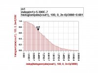
Simulated Noise Floor for JFET MC Amp
Here is the simulated noise PDF for the MC amp with a 20 - 20KHz BPF applied. With a gain of approx 14, the equivalent noise referenced to the input stage is 0.27 nV/sqrt(hz). This was simulated with the input shorted
Here is the simulated noise PDF for the MC amp with a 20 - 20KHz BPF applied. With a gain of approx 14, the equivalent noise referenced to the input stage is 0.27 nV/sqrt(hz). This was simulated with the input shorted
Attachments
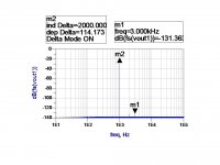
Simulated Distortion for the MC Amp
Here is the simulated distortion for a 20 mVPP input into the MC amp. 20 mVPP is, of course, considerably in excess of what an MC cartridge can deliver. At lower input levels the distortion measurement is limited by the amp's noise floor. Remember also, that this is a zero GFB design.
Here is the simulated distortion for a 20 mVPP input into the MC amp. 20 mVPP is, of course, considerably in excess of what an MC cartridge can deliver. At lower input levels the distortion measurement is limited by the amp's noise floor. Remember also, that this is a zero GFB design.
Attachments
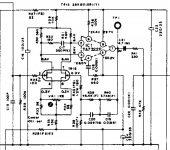
i m using an AKAI preamp (that i did save from being scrapped at the local crapyard !!) that use 2SK150 dual fets at the input.
This one PR-A04?
included a Sharp for fun
Attachments
Hi,
I wonder why You use a differential input stage structure in first place?
Why not use the simpler complementary grounded source instead?
It'd require 6 JFETs and 2 resistors less for the same outcome.
At first thought the only difference could be lower pssr and a phase inversion of the output.
I'd say the differential Input comes handy if we have to deal with (and/or combine) two signals at the same.
If we only have to deal with a single signal there's no advantage over a SE structure, but added complexity and hassle.
The lower THD is imho only due to complementary action and not because of the differential Input structure.
jauu
Calvin
Last edited:
- Status
- This old topic is closed. If you want to reopen this topic, contact a moderator using the "Report Post" button.
- Home
- Source & Line
- Analogue Source
- Novel Topology MC pre-preamp