I'm building a phono preamp, and trying to find a way to reduce the distortion (and noise) due to the impedance non-linearity at the inputs. This discussion is primarily about MM cartridges which have a high impedance that rises to 10's of thousands of Ohms at high frequencies due to the inductance. Also for this discussion, ignore any RIAA feedback networks and assume a flat gain stage.
Using the usual voltage amplifying input stage with negative feedback, you want the feedback resistance very low to reduce noise, so the - input typically sees less than 100 Ohms resistance. This impedance mismatch will cause a form of common mode distortion, typically close to 0.1% at high frequencies with almost all opamps. For examples showing this, see Samuel Groner's "Operational Amplifier Distortion" document, specifically the "Input Impedance Linearity" graphs, available on his web site:
SG-Acoustics · Samuel Groner · IC OpAmps
Or, see Figure 6-40 on page 6.53 from Analog Devices "Op Amp Applications" document, available from their web site.
ADI - Analog Dialogue | Op Amp Applications Handbook
(sorry I'm not able to copy images from these documents)
Here are some possible solutions:
1. Match input impedances. Insert an impedance network in the feedback leg to match the input impedance (MM cartridge plus load). See figure below. Obviously not a very practical solution that will match all cartridges, but will a network with "typical" values for a MM cartridge be better than nothing? Believe it or not, some preamp products have incorporated actual cartridges into the feedback path to reduce distortion! Again, not very practical in my opinion.

2. Bootstrapping. For example, see Analog Devices AN-232. Very interesting approach, but I am leery of a method that bootstraps the IC substrate, that is, it appears to modulate the minus supply with a version of the input signal. It is claimed to be highly effective, but I wonder what kinds of side effects it may have? Anyone try this? And what if I want to use external transistors at the inputs to reduce the input noise, will bootstrapping work for that plus the opamp too?

3. Instrumentation Amp configuration with balanced inputs. See example of classic 3 Opamp instrumentation implementation below. This approach is supposed to reduce common mode noise, but will it also cancel out non-linear common mode distortion? I have not seen any distortion plots for instrumentation amps, so I don't know how effective this approach will be. Anyone know?

Are there any other approaches? (Don't tell me to stick to MC cartridges.)
Using the usual voltage amplifying input stage with negative feedback, you want the feedback resistance very low to reduce noise, so the - input typically sees less than 100 Ohms resistance. This impedance mismatch will cause a form of common mode distortion, typically close to 0.1% at high frequencies with almost all opamps. For examples showing this, see Samuel Groner's "Operational Amplifier Distortion" document, specifically the "Input Impedance Linearity" graphs, available on his web site:
SG-Acoustics · Samuel Groner · IC OpAmps
Or, see Figure 6-40 on page 6.53 from Analog Devices "Op Amp Applications" document, available from their web site.
ADI - Analog Dialogue | Op Amp Applications Handbook
(sorry I'm not able to copy images from these documents)
Here are some possible solutions:
1. Match input impedances. Insert an impedance network in the feedback leg to match the input impedance (MM cartridge plus load). See figure below. Obviously not a very practical solution that will match all cartridges, but will a network with "typical" values for a MM cartridge be better than nothing? Believe it or not, some preamp products have incorporated actual cartridges into the feedback path to reduce distortion! Again, not very practical in my opinion.
2. Bootstrapping. For example, see Analog Devices AN-232. Very interesting approach, but I am leery of a method that bootstraps the IC substrate, that is, it appears to modulate the minus supply with a version of the input signal. It is claimed to be highly effective, but I wonder what kinds of side effects it may have? Anyone try this? And what if I want to use external transistors at the inputs to reduce the input noise, will bootstrapping work for that plus the opamp too?
3. Instrumentation Amp configuration with balanced inputs. See example of classic 3 Opamp instrumentation implementation below. This approach is supposed to reduce common mode noise, but will it also cancel out non-linear common mode distortion? I have not seen any distortion plots for instrumentation amps, so I don't know how effective this approach will be. Anyone know?
Are there any other approaches? (Don't tell me to stick to MC cartridges.)
the dielectric isolated cascode input of the OPA627 is a jfet monolithic op amp example from the opamp_distortion paper with low input impedance distortion
a simple circuit condition is maximize the supply V to reduce the input Z modulation
the nonlinear cm input impedance distortion mechanism at mm phono cart signal levels is not likely to be easily measurable:
the opamp_distortion paper uses 100 K input Z and unity gain in the nolinear input impedance test circuit, I can't find the test level explicitly stated for the input impedance test but +20 dBu seems to be the nominal test source setting
for mm phono cart the signal level is ~100x less and the source Z is at least 10x less than the test Z, for predominantly 2nd order distortion the expected distortion is directly proportional to level so the best estimate is that this distortion would be 1000x less than the plots
with the -60 dB correction for application's <100 mV input swing and <10K input impedance imbalance the AD823 (as a typical fet input op amp) input distortion would be below the noise floor in the opamp_distortion paper plot - and the OPA627 input impedance distortion is over an order of magnitude lower under the test conditions
a low noise op amp like the AD743/745 will have larger input device C and proportionately larger input nonlinearity but even at 10x greater than the AD823 or OPA134 input impedance distortion it would hugely less than any of a number of phonograph mastering, cutting, playback distortion mechanisms
output loading distortion can easily be larger with the low Z feedback required for low noise - so a output buffer in the loop is necessary to get to where its worth worrying about input nonlinear C
added loop gain in the multiloop output buffer like Jung shows improves the transfer linearity too
Last edited:
Have you looked at the designs of Douglas Self for an ultra low noise front end ?
IMO Dougs design is about as good as gets and addresses many issues and problems.
Around page 53 here,
Self on Audio - Google Books
IMO Dougs design is about as good as gets and addresses many issues and problems.
Around page 53 here,
Self on Audio - Google Books
Thanks guys, for your inputs.
What I want to do is use external JFETs to reduce both the input voltage and current noise. The problem is these low noise JFETs have very large capacitances, (yes, cascoding will help, but not eliminate the capacitance) more than ten times than those found in typical op amps, so I fear that the distortion effects will be magnified compared to the op amp distortion tests. Unfortunately most JFETs don't have access to the substrate for bootstrapping, though the obsolete 2SK389 and I think the LSK389 do have substrate pins.
I don't agree that a MM phono input's impedance is less than 10 times the 100K Ohms used in the Opamp test setups. Most MM's have very high inductance for example AT155LC about 500mH, or Stanton 681 910mH, resulting in around 30K Ohms at 10-20KHz (even with a 47K load in parallel), not that far from the test setup (those high impedances are a reason for my wanting to use JFETs for lower current noise). I do agree that the input levels will be smaller for a phono cartridge, on the order of 100mv peak, so that will help minimize the distortion. Yes, yes, phono distortions are gross, on the order of 1%, but that's no reason to use a poor opamp design for a phono stage, I would like to reduce the distortion as much as possible if only for my own peace of mind.
I have found another example of boostrapping to reduce distortion, by Dimitri Danyuk published in Electronic Design -
Supply Bootstrapping Reduces Distortion In Op-Amp Circuits
This is also discussed in another old thread.
Have you looked at the designs of Douglas Self for an ultra low noise front end ?
IMO Dougs design is about as good as gets and addresses many issues and problems.
Around page 53 here,
Self on Audio - Google Books
Thanks, Mooly, I don't have that book but I do have Self's Power Amp book, and his new Small Signal book on order - can't wait for that one to arrive, hopefully it will have many good design ideas that will address these and other issues.
I have received several responses questioning whether MM cartridges really do have impedances on the order of 30K Ohms at high frequencies. You can look up the equations for calculating R,L,C impedances in any introductory electronics or physics textbook. Plug in the numbers for a MM cartridge, typically R(DC) from 500 to 1000 Ohms, L from 500 too 1000 mH, and C(load) typically 200 to 300 pF recommended, plus 47K R(load), and you should get in the neighborhood of 30-40K Ohms at 10KHz (in answer to a question, the capacitive load helps to dampen and flatten the frequency response peak, but does not cancel out the impedance at 10-20KHz; if it were large enough to do so, the cartridge's high frequency response would be seriously reduced). See for example Dennis Colin's preamp article from audioXpress, an extract quoted below -
http://www.audioxpress.com/magsdirx/ax/addenda/media/colin2774.pdf
"I measured the impedance of a Shure R27E cartridge. Although old and inexpensive,its impedance is typical: 635Ω + 631mH. Paralleled with this preamp’s 47k5 load, the impedance seen by the preamp at 1kHz is 943Ω (resistive) + j3k84 (inductive); impedance magnitude is 3k95. But at 10kHz, z = 19k5 + j23k; magnitude is 30k2.
I had first tried an AD797 op amp alone (no JFET) at the input. With a low source impedance such as an MC cartridge provides, all was fine. But with the MM cartridge, the noise was about 8dB higher than with the JFET input; plus (rather, a negative) the noise peaked around 10kHz. Too much and hissy! The reason is the bipolar op amp’s input current noise. Now, 2pA/√Hz might not sound like much, but when multiplied by the loaded cartridge’s 30k impedance magnitude at 10kHz, a noise voltage term of 60nV/√Hz undesirably appears! This is 10.5dB higher (at 10kHz) than the 18nV/√Hz noise of the loaded cartridge’s 19k5 resistive component. Combined, the resulting NF is 10.8dB at 10kHz. The JFET reduced the NF to 0.3dB."
On another topic, here is Mike P's view on the drawbacks of bootstrapping the supply rail, taken from the other DIY (Simple Machines) Forum's thread on Sam Groner's
OpAmp Measurement Series
"there is a lurking problem with almost every version of modulated rail or bootstraped cascode distortion reducing mechanism I have studied, ugly overload characteristics. Even if care is taken to keep the circuit from going into oscillation or outright blowing transistors, you still seem to always end up with at least spikes of current on the supply rails as protection diodes start to conduct. and there is the sudden shift in conditions caused when a rail driver clips and the voltage across the active device starts to change with the signal. imagine a capacitance multiplier for each rail, with the shunt capacitors connected to the output of a common mode voltage follower instead of ground. When the followers clip It doesnt cause gross distortion but it far from ideal. this is not easy to indicate with a clip LED and changes with gain."
the opa627 still looks like the input impedance nonlinearity is going to be below the noise floor with 30 KOhm source peak using the opamp_distortion paper's numbers
bootstrapping `~100 mV signal in a gain ~10 circuit with +/15 V supplies is not going to have the issues of clipping a bootstrapped unity gain follower against the supply rails so I think as long as startup issues are controlled there is little chance of signal related bootstrap clipping issues
Dimitri's Fig 3 ps bootstrap op amp U2 will never clip, if U1 clipping causes excess ps pin current that draws down C9,10 unacceptably then adding shunt regulation (Zener or TL431) with enough bias current could eliminate the consequences)
http://archive.electronicdesign.com/files/29/19609/fig_03.gif
the opa627 still looks like the input impedance nonlinearity is going to be below the noise floor with 30 KOhm source peak using the opamp_distortion paper's numbers
Thanks for pointing out the opa627, which looks like it uses bootstrapping to control the impedance linearity distortion. I don't know if it will have distortion below the noise floor - below 1KHz, yes, but above, it's hard to tell from the graph (see green trace below) since it doesn't seem to specify the signal level. At any rate, the distortion seems fairly low compared to other op-amps. The big drawback for me is that the opa627 costs about US$25 each in small quantities (ouch!). At that price I think I'll try to roll my own bootstrapping circuit. I just wish that there was more information on bootstrapping - all the published circuits I could find don't give a lot of DIY design information (how much bootstrapping to use for different gains or supply voltages, what if you use discrete transistors, what value current sources or voltage regulators to use for the Danyuk circuit, etc). It seems those articles were written for expert analogue designers!

any composite op amp circuit is pretty rare despite Jerald Graeme and Walt Jung's including chapters on multiloop amps in their books
op amp supply bootstrapping is doubly rare - scattered articles, a few per decade mean the technique is not widely known or used
in diy audio there is an additional bias towards using discrete in any application - and certainly when there is any question about op amp performance limitations in the application
circuits similar to the audioXpress article's discrete fet input working inside the feedback loop with an op amp are probably the most used class of discrete/op amp hybrid composite amplifiers
Thanks, Mooly, I don't have that book but I do have Self's Power Amp book, and his new Small Signal book on order - can't wait for that one to arrive, hopefully it will have many good design ideas that will address these and other issues.
The "small signal book" may have exactly what you are after... there is a section on phono front ends that involves using an opamp to synthesise the load impedance required... all in the quest for lower noise.
Wait 'till you get the book
")
I hope to explain some of the causes and solutions for distortion due to impedance non-linearity. Keep in mind that I am not an analog or IC design expert. I'm just posting what I've learned from textbooks, articles, and internet forums. First, some information on JFETs. Below are pictures of the physical structure of how JFETs are fabricated. The first example is an N channel discrete JFET. Note how the N channel is sandwiched between the two P gate layers. You can see from this diagram how there can be significant capacitances between the gate and the source and drain.

Now a P-channel JFET fabricated on a bipolar IC process with a P substrate (P channel JFETs are more common than N channel in op amps probably because they are more compatible with the bipolar process). Note that in addition to the previously mentioned capacitances, there can also be a significant capacitance between the gate and the substrate for an IC. Normally the substrate in an IC is connected to the negative supply voltage.

Now here is a diagram of a simplified small signal model for a JFET which includes these capacitances:

Cgss: gate to substrate capacitance
Cgs: gate to source capacitance
Cgd: gate to drain capacitance
The bad things about these capacitances is one, they can be large (especially with low noise JFETs), affecting frequency response, and two, the capacitance varies significantly with voltage, causing distortion (bipolar transistor capacitances don't very as much, but it can still be a problem). You can see the effect of voltage on the JFET capacitances on these graphs taken from the 2SK170 data sheet:

Note that most data sheets show the capacitances as
Ciss: common source input capacitance
Crss: common source reverse transfer capacitance
because that is what they measure from the device terminals. Here are the equations to translate between the two sets of capacitances:
Crss = Cgd
Ciss = Cgd + Cgs
The gate to substrate capacitance in ICs is rarely if ever published, but seems to the predominant one at least for the usual bipolar junction insulated process (which typically has the P substrate shown above). Some op amps use a dielectrically isolated process which isolates devices from each other, and I'm guessing may reduce the gate to substrate capacitance. The Analog Devices App Note 232 applies to the process having the gate to substrate capacitance, and I don't know if it will apply to op amps using other processes.
Now, to reduce the non-linear effects of the capacitances, there are some things you can do:
1. Use devices that have low capacitances to begin with (unfortunately, this usually means more noise).
2. Operate with as low a source impedance as you can (this pushes the distortion effects to frequencies hopefully above the band of interest, if R*C is low enough), and try to balance the input impedances.
3. Operate at as high a voltage as you can to reduce the capacitances (note that in Groner's op amp distortion tests the input impedance linearity distortion usually goes down with higher supply voltages).
4. Try to operate at a constant voltage - this is where bootstrapping comes in.
Here is an explanation of what the bootstrap circuit in AN-232 does. If you go through the equations, you find that the bootstrap/substrate voltage is tracking the input voltage so that Vin-V(substrate) is kept at a constant voltage. This maintains a constant voltage across the input to substrate capacitor to minimize its non-linear effects. Note this trick does not maintain a constant voltage for the other JFET capacitances (Cgs, Cgd), but in the AD744 at least, their effects seem to be much less than the substrate capacitance.
Now a P-channel JFET fabricated on a bipolar IC process with a P substrate (P channel JFETs are more common than N channel in op amps probably because they are more compatible with the bipolar process). Note that in addition to the previously mentioned capacitances, there can also be a significant capacitance between the gate and the substrate for an IC. Normally the substrate in an IC is connected to the negative supply voltage.
Now here is a diagram of a simplified small signal model for a JFET which includes these capacitances:
Cgss: gate to substrate capacitance
Cgs: gate to source capacitance
Cgd: gate to drain capacitance
The bad things about these capacitances is one, they can be large (especially with low noise JFETs), affecting frequency response, and two, the capacitance varies significantly with voltage, causing distortion (bipolar transistor capacitances don't very as much, but it can still be a problem). You can see the effect of voltage on the JFET capacitances on these graphs taken from the 2SK170 data sheet:
Note that most data sheets show the capacitances as
Ciss: common source input capacitance
Crss: common source reverse transfer capacitance
because that is what they measure from the device terminals. Here are the equations to translate between the two sets of capacitances:
Crss = Cgd
Ciss = Cgd + Cgs
The gate to substrate capacitance in ICs is rarely if ever published, but seems to the predominant one at least for the usual bipolar junction insulated process (which typically has the P substrate shown above). Some op amps use a dielectrically isolated process which isolates devices from each other, and I'm guessing may reduce the gate to substrate capacitance. The Analog Devices App Note 232 applies to the process having the gate to substrate capacitance, and I don't know if it will apply to op amps using other processes.
Now, to reduce the non-linear effects of the capacitances, there are some things you can do:
1. Use devices that have low capacitances to begin with (unfortunately, this usually means more noise).
2. Operate with as low a source impedance as you can (this pushes the distortion effects to frequencies hopefully above the band of interest, if R*C is low enough), and try to balance the input impedances.
3. Operate at as high a voltage as you can to reduce the capacitances (note that in Groner's op amp distortion tests the input impedance linearity distortion usually goes down with higher supply voltages).
4. Try to operate at a constant voltage - this is where bootstrapping comes in.
Here is an explanation of what the bootstrap circuit in AN-232 does. If you go through the equations, you find that the bootstrap/substrate voltage is tracking the input voltage so that Vin-V(substrate) is kept at a constant voltage. This maintains a constant voltage across the input to substrate capacitor to minimize its non-linear effects. Note this trick does not maintain a constant voltage for the other JFET capacitances (Cgs, Cgd), but in the AD744 at least, their effects seem to be much less than the substrate capacitance.
ps bootstrapping or a bootstrapped cascode should reduce/eliminate common mode deltaV
differential mode deltaV is reduced by high loop gain
Dimitri's positive gain circuit with input common mode bootstrapping should hugely reduce impedance modulation and distortion as shown in his plots - although he boostraps a bjt input op amp and it may be the common mode nonlinearity term reduction that is being seen in the plots
if you want to use op amps then the real low noise option is the AD743/745
if you can accept some lf s/n loss then the AD8655 is cheap but would really need an output stage with gain in the loop to achieve acceptable headroom
for a really low noise discrete SE input the audioXpress circuit could be modified with bootstrapping of the jfet input drain resistor supply and op amp ps
but these aren't textbook circuits
differential mode deltaV is reduced by high loop gain
Dimitri's positive gain circuit with input common mode bootstrapping should hugely reduce impedance modulation and distortion as shown in his plots - although he boostraps a bjt input op amp and it may be the common mode nonlinearity term reduction that is being seen in the plots
if you want to use op amps then the real low noise option is the AD743/745
if you can accept some lf s/n loss then the AD8655 is cheap but would really need an output stage with gain in the loop to achieve acceptable headroom
tried some digitizing sw - "plot digitizer" on sourceforge
I suppose the main lesson of AI is how hard it is to make a computer do things that are obvious and trivial for humans but it seems like these programs could be a little more automated - lots of hand trimming of the points was required
mathcad for display:
jfet solid lines, low noise cmos dashed
Input Voltage Noise vs Frequency from manufacturer's data sheets
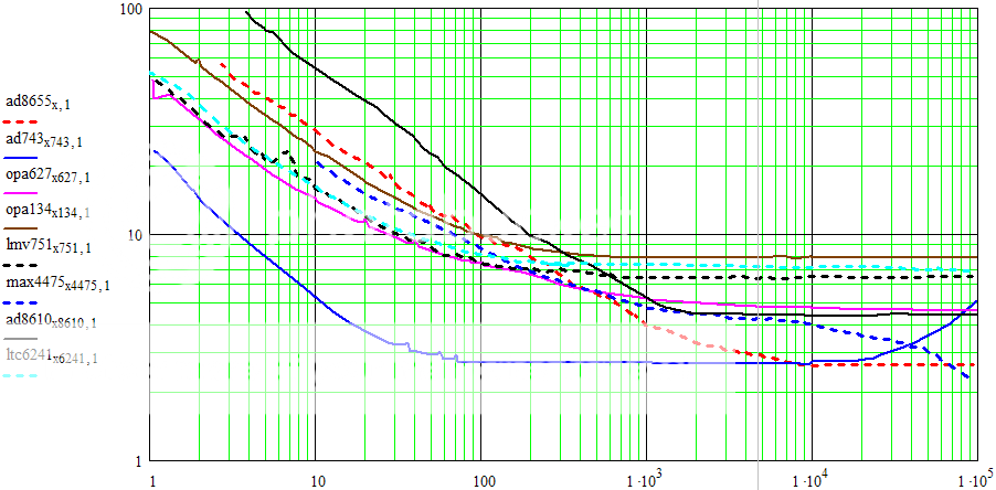
no warranty of correctness expressed or implied but it still looks like the ad743 is the one to beat - thank Scott Wurcer
for a really low noise discrete SE input the audioXpress circuit could be modified with bootstrapping of the jfet input drain resistor supply and op amp ps
but these aren't textbook circuits
Here are some examples of bootstrapping a cascoded JFET input circuit to reduce impedance linearity distortion. First, the input circuit of the OPA627 illustrates the idea. This opamp shows well controlled impedance linearity distortion according to Sam Groner's tests.

Q3-Q6 provide the cascode for the JFETs Q1, Q2 (I believe that Q5,Q6 act as current repeaters to send the I1 current to Q3,Q4). One of the main reasons for using a cascode is to reduce the effective capacitance. Without cascoding, a common source circuit's Crss/Cgss (see JFET model in previous post) is in effect multiplied by the JFET gain, this can result in hundreds of pF! The cascode load for the JFET pretty much eliminates this effect ("Miller effect"). B1, in conjuction with Q7,Q8, and current sink I2 provide the bootstrapped bias voltage for the cascode. You will note that the bias voltage is referenced to the JFET source instead of to ground, so it is in effect bootstrapped to the input voltage to provide a near constant voltage across the JFET.
Here is a cascoded circuit without bootstrapping (reference voltage to ground) with spice simulation of the JFET Vds variation. This particular circuit uses resistor loads instead of a current mirror like in the OPA627 in order to match a later published circuit that I will compare with. The simulation was done with generic 2N3904 and 2N5485 transistors instead of better quality parts because that's what was available in my simulator library.


You will note that without bootstrapping, the voltage across the JFET follows the input voltage variations, so there could be significant JFET capacitance/voltage variation and distortion.
Now a cascoded circuit with a bootstrapped reference voltage, similar in concept to the OPA627 circuit, and the simulated voltage variation.


Note the scale of the voltage variations, it is actually much less than the non-bootstrapped circuit, and on the order of a few millivolts. Also note that I was forced to run a zener reference (D1) at less than an ideal current because of simulator library limitations, so performance could be better than this if you used a micropower voltage reference like a LMV431 for example. Another possibility is a reversed biased transistor which often works well as a micropower zener. You want to use a micropower reference so you don't affect the bias current for the JFETs so much.
Another bootstrapped circuit using a JFET bias as published by Analog Devices in their "Op Amp Applications" manual (chapter 6), with simulation results (I used a 2N5432, which has a Vgs pinchoff of around -5 volts for the JFET bias).


This appears to work quite well to limit the voltage variation for such a simple circuit. The issue with this method is that you need to select the JFET for its Vgs (look for a large Vgs off or pinchoff value) and you may be limited to a bias voltage of around 4 or 5 volts as there aren't many JFETs with larger Vgs values. In theory, you may be able to stack two JFETs to get a larger bias voltage, and it seems to work in a simulation I ran.
Now, slightly off topic as it isn't a phono preamp circuit, but here's an interesting example of a cascoded circuit (non-bootstrapped as far as I can tell, but the schematic is too blurry to say for sure) from a Hafler power amp. It is more sophisticated than usual for a power amp input. Note that it actually has bias voltages for the optional 2SK389/2SJ109 dual transistor subtrates ("S/S"). The subtrate bias voltages seem to be set at half the cascode voltage, I wonder how they determined that?

Q3-Q6 provide the cascode for the JFETs Q1, Q2 (I believe that Q5,Q6 act as current repeaters to send the I1 current to Q3,Q4). One of the main reasons for using a cascode is to reduce the effective capacitance. Without cascoding, a common source circuit's Crss/Cgss (see JFET model in previous post) is in effect multiplied by the JFET gain, this can result in hundreds of pF! The cascode load for the JFET pretty much eliminates this effect ("Miller effect"). B1, in conjuction with Q7,Q8, and current sink I2 provide the bootstrapped bias voltage for the cascode. You will note that the bias voltage is referenced to the JFET source instead of to ground, so it is in effect bootstrapped to the input voltage to provide a near constant voltage across the JFET.
Here is a cascoded circuit without bootstrapping (reference voltage to ground) with spice simulation of the JFET Vds variation. This particular circuit uses resistor loads instead of a current mirror like in the OPA627 in order to match a later published circuit that I will compare with. The simulation was done with generic 2N3904 and 2N5485 transistors instead of better quality parts because that's what was available in my simulator library.
You will note that without bootstrapping, the voltage across the JFET follows the input voltage variations, so there could be significant JFET capacitance/voltage variation and distortion.
Now a cascoded circuit with a bootstrapped reference voltage, similar in concept to the OPA627 circuit, and the simulated voltage variation.
Note the scale of the voltage variations, it is actually much less than the non-bootstrapped circuit, and on the order of a few millivolts. Also note that I was forced to run a zener reference (D1) at less than an ideal current because of simulator library limitations, so performance could be better than this if you used a micropower voltage reference like a LMV431 for example. Another possibility is a reversed biased transistor which often works well as a micropower zener. You want to use a micropower reference so you don't affect the bias current for the JFETs so much.
Another bootstrapped circuit using a JFET bias as published by Analog Devices in their "Op Amp Applications" manual (chapter 6), with simulation results (I used a 2N5432, which has a Vgs pinchoff of around -5 volts for the JFET bias).
This appears to work quite well to limit the voltage variation for such a simple circuit. The issue with this method is that you need to select the JFET for its Vgs (look for a large Vgs off or pinchoff value) and you may be limited to a bias voltage of around 4 or 5 volts as there aren't many JFETs with larger Vgs values. In theory, you may be able to stack two JFETs to get a larger bias voltage, and it seems to work in a simulation I ran.
Now, slightly off topic as it isn't a phono preamp circuit, but here's an interesting example of a cascoded circuit (non-bootstrapped as far as I can tell, but the schematic is too blurry to say for sure) from a Hafler power amp. It is more sophisticated than usual for a power amp input. Note that it actually has bias voltages for the optional 2SK389/2SJ109 dual transistor subtrates ("S/S"). The subtrate bias voltages seem to be set at half the cascode voltage, I wonder how they determined that?
Is the noise you guys are speaking of coming from the cartridge when you hold your hand close to it?? This is the trouble I'm having with my Realistic Lab 440 with a Sure cartridge. I've check to be sure the ground is connected securely and that the RCA cables are not touching, but when I get close to the cartridge, it makes a loud audio buzz thats almost like feedback. Does then cartridge need to be looked at or changed, or is there a chance it needs to be demagnetized?
Is the noise you guys are speaking of coming from the cartridge when you hold your hand close to it?? This is the trouble I'm having with my Realistic Lab 440 with a Sure cartridge. I've check to be sure the ground is connected securely and that the RCA cables are not touching, but when I get close to the cartridge, it makes a loud audio buzz thats almost like feedback. Does then cartridge need to be looked at or changed, or is there a chance it needs to be demagnetized?
This is a very, very off topic post..
This thread has nothing at all to do with your issue. Does it otherwise work normally or does it hum a lot when playing? You shouldn't have any discernible increase in noise when your hands are in proximity of the cartridge - it sounds to me like the shield on your cartridge if present is not grounded or that the arm tube itself is no longer properly grounded. (Look for broken or corroded internal ground wiring connections.) Does your table have a ground wire and is it connected? MM cartridges like your Shure should never be demagnetized and IMHO this is of very limited value on most MC types as well.Any Mod want to move this and the original question (Post #15) to a new thread?
Last edited:
- Status
- This old topic is closed. If you want to reopen this topic, contact a moderator using the "Report Post" button.
- Home
- Source & Line
- Analogue Source
- Fixing Phono Preamp Distortion due to Impedance Nonlinearity