This thread is getting nowhere....
no decisions can be made...trafo no trafo, balanced, single ended, complementary power supply...servo coupling cap...All is still in the game...all ends are open...and no clear design objectives...apart from low noise figures
mr curl is central in this and was mostly looking for a n-channel type design....some circuits was brought forward..and worked a little...then all blew up again with no sense of direction...
Hi,
Some here have been cooking off-board. Expect some results sooner or later...
Ciao T
PS, just discovered that I can get easily get the LH0032, does anyone know if the noise is low enough for MM Phono?
This thread is getting nowhere...
Some here have been cooking off-board. Expect some results sooner or later...
Ciao T
PS, just discovered that I can get easily get the LH0032, does anyone know if the noise is low enough for MM Phono?
MiiB, Bob Cordell is coming around to the same idea of an N channel jfet design, with perhaps differential input as an optional extra, which is what I tried to promote a short while ago and may be an optimal way to make a 'buildable' input stage for most people here, with high quality, flexibility, yet low complexity. We did get sidetracked with Vendetta type complementary designs, etc, that are getting harder and more expensive to get parts for, that require matching of the complements, at the the very least, and servoing. Perhaps we can once again, get back on track.
It´s a bit noisy at 40nV/qHz.
8001301Z (M.S. Kennedy) - Operational Amplifier, Replacement For LH0032 | HTML.datasheet
8001301Z (M.S. Kennedy) - Operational Amplifier, Replacement For LH0032 | HTML.datasheet
It´s a bit noisy at 40nV/qHz.
8001301Z (M.S. Kennedy) - Operational Amplifier, Replacement For LH0032 | HTML.datasheet
THe U440 is about 5nV/V^ Hz at 1 kHz....
It´s a bit noisy at 40nV/qHz.
8001301Z (M.S. Kennedy) - Operational Amplifier, Replacement For LH0032 | HTML.datasheet
Spare parts for 1979 vintage military gear. Check the price, probably > $100.
Joachim,
Thanks, I tried to find Ein, it's not on the common datasheets for the Calogic/National part. However the Calogic/National parts use a different design, without source degeneration, compare to the one shown...
The input FET's in the LH0032 run without degeneration and per national have 3.5mA/V transconductance. This should be 280 Ohm equivalent per Fet, so at least IN THEORY I would expect around 3nV|/Hz Ein for the original...
But no specification I can find.
Ciao T
PS, I can get tested equipment pulls for next to nothing...
It´s a bit noisy at 40nV/qHz.
8001301Z (M.S. Kennedy) - Operational Amplifier, Replacement For LH0032 | HTML.datasheet
Thanks, I tried to find Ein, it's not on the common datasheets for the Calogic/National part. However the Calogic/National parts use a different design, without source degeneration, compare to the one shown...
The input FET's in the LH0032 run without degeneration and per national have 3.5mA/V transconductance. This should be 280 Ohm equivalent per Fet, so at least IN THEORY I would expect around 3nV|/Hz Ein for the original...
But no specification I can find.
Ciao T
PS, I can get tested equipment pulls for next to nothing...
Last edited:
Spare parts for 1979 vintage military gear. Check the price, probably > $100.
Calogic LH0032 can be had at Future Electronics for about $18 each.

Hi,
Actually, balanced lines do no such things.
They only suppress COMMON MODE noise, any differential mode noise is as bad as with an SE Circuit.
In the typical 1-2m Cable run of sensible cable that minimises differential noise (twisted pair, coaxial) from the tonearm the common mode noise pickup that balanced lines could deal with is minimal. So the fact that we have different impedances to ground at the two different conductors is is of very little, if any consequence.
Ciao T
The only way this comment makes sense is if you believe cables actually make noise!
Calogic LH0032 can be had at Future Electronics for about $18 each.
Not MIL-883B, these are hybrid dinosaurs.
Last edited:
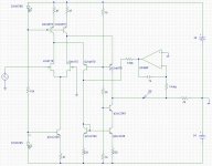
Bappe's suggestion in #399, on page 40, on April 21, is really a good place to start. It can be both: balanced and unbalanced (in some situations). Open loop or closed loop.
Far more versatility than a simple IC. I again, recommend it.
Not every design approach is optimum or even useful, any more than autos would do better with 6 wheels, or 3 for that matter.
Far more versatility than a simple IC. I again, recommend it.
Not every design approach is optimum or even useful, any more than autos would do better with 6 wheels, or 3 for that matter.
Looking at the circuit #399....I came to think that i would be possible to add a little feedback...and maybe even let the upper pole and third constant be part of the circuit..
personally I would omit the servo..because a Riaa really need the low cut to take the warp out...
personally I would omit the servo..because a Riaa really need the low cut to take the warp out...
Attachments
Last edited:
This is one possible direction. There are others.
Usually, adding the 75us RC rolloff above 2KHz, just after the first stage, takes the mistracking 'pulse' down to a risetime limited square wave, the very thing that most of you think about as being a typical source. This is most important, in order to make it relatively easy for the global negative feedback to not do anything adverse to audio quality.
Usually, adding the 75us RC rolloff above 2KHz, just after the first stage, takes the mistracking 'pulse' down to a risetime limited square wave, the very thing that most of you think about as being a typical source. This is most important, in order to make it relatively easy for the global negative feedback to not do anything adverse to audio quality.
- Status
- This old topic is closed. If you want to reopen this topic, contact a moderator using the "Report Post" button.
- Home
- Source & Line
- Analogue Source
- Parasound JC3 Phono