As my first diy pcb project i want to build a good but simple phono amp for mm/mc cartridges. I have decided to build the Hagtech bugle phono amp.
But i want to make the pcb myself because i hope i will learn something of it.
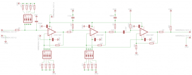
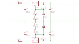
As mentioned i want to use it with mm and mc cards so i want to make it adjustable with dil switches. I am new to pcb software so i did a first afford to redraw the bugle schematic and a powersupply. I found this topic Lower noise in the Bugle-very low res value, Xtreme accuracy about lowering the noise by lowering the resistors.
Attached are the two schematics i made so far.
Hope you're willing to comment on this:
- Is drawing going in the right direction or is it completely wrong?
- I think I am going to use Panasonic fc caps next to the opamps and for the powersupply, is this a good choice?
- Is it oke to use wima caps for the filtering or are there better alternatives?
- The gain is set at the first two opamps, with a dil switch for each opamp, is it possible to set both gains with just one switch?
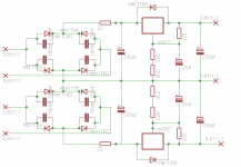
- What is a good choice for the diode's to use as a rectifier?
Thanks,
But i want to make the pcb myself because i hope i will learn something of it.
As mentioned i want to use it with mm and mc cards so i want to make it adjustable with dil switches. I am new to pcb software so i did a first afford to redraw the bugle schematic and a powersupply. I found this topic Lower noise in the Bugle-very low res value, Xtreme accuracy about lowering the noise by lowering the resistors.
Attached are the two schematics i made so far.
Hope you're willing to comment on this:
- Is drawing going in the right direction or is it completely wrong?
- I think I am going to use Panasonic fc caps next to the opamps and for the powersupply, is this a good choice?
- Is it oke to use wima caps for the filtering or are there better alternatives?
- The gain is set at the first two opamps, with a dil switch for each opamp, is it possible to set both gains with just one switch?
- What is a good choice for the diode's to use as a rectifier?
Thanks,
Attachments
Last edited:
Thanks, i will have a look at that opamp, maybe i can try the LME49710, some people are raving about them?
Do you mean the 39 ohm at the input or the one after the last opamp, or both?
Any comments on the caps for the filter and the diode's ?
The regulator in the supply is an lm317.
Do you mean the 39 ohm at the input or the one after the last opamp, or both?
Any comments on the caps for the filter and the diode's ?
The regulator in the supply is an lm317.
the 39 ohm at the input add noise. i whould use a 75 ohm with 100kOhm to ground at the ouput. the LME49710 is ca. 5dB more noisy then the other options i mentioned but much better then the OPA134 in that aplication. it (the LME710) is a very good op other wise and a great value. i could live with it´s noise performance when your cartridge puts out more then 0.5mV. i think the spec is 1.9nVqHz compared to the 8nVqHz of the OPA134. a clear 12dB improvement. i use Pannasonic FM and Rubicon ZLH capacitors. both are not expensive at all and have great dynamics and resolution. if you like a more soft presentation go for the much more expensive Nichicon Muse or Elna Silmic.
After the 220uF you could put some coils and then use elcaps again ( up to 10.000 uF) bypassed with something like 1uF foil. i have 25mH coils with 4 Ohm impedance and sell them for 15 Euro plus shipping a piece. selected pairs (better then 2%) or quadruples cost more but that is not neccesary here. You will hear a big reduction of low frequency grunge and get lower intermodulation distortion. A fully discreet circuit whould react even more sensitive. Op amps like the ones you are using have good PSR but still you can hear the quality of the PSU. i whould also bypass the op amps locally with 100 - 220uF and 100nF NPO or COG.
After the 220uF you could put some coils and then use elcaps again ( up to 10.000 uF) bypassed with something like 1uF foil. i have 25mH coils with 4 Ohm impedance and sell them for 15 Euro plus shipping a piece. selected pairs (better then 2%) or quadruples cost more but that is not neccesary here. You will hear a big reduction of low frequency grunge and get lower intermodulation distortion. A fully discreet circuit whould react even more sensitive. Op amps like the ones you are using have good PSR but still you can hear the quality of the PSU. i whould also bypass the op amps locally with 100 - 220uF and 100nF NPO or COG.
Thank you for your reaction. By using coils this project becomes al little bit to expensive, i thought that if i want a simple and affordable powersupply this one was a good one to start with, maybe some tweaking can make it a little bit better
As you can see i used mkp caps to bypass the diodes, is this a good choice? I you look at the schematic i have posted on the first post of this topic, you can see that i bypassed the V+ and V- of the opamps to the ground. If i understand you correct you advise to put a little cap parallel to these caps?
-Is a ceramic cap better than a mkp cap for this purpose?
-I cannot find any information about bypassing in the lme datasheet, the only hint i found was a schematic in that datasheet where they used 47uf to bypass, how do i determine the best value to use?
- Status
- This old topic is closed. If you want to reopen this topic, contact a moderator using the "Report Post" button.
- Home
- Source & Line
- Analogue Source
- Bugle phono preamp with gain and source impedance adjustment.