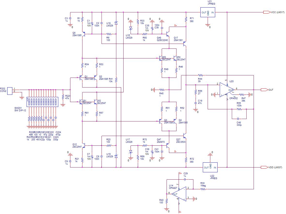
Here's the HPS4.0 phono stage schematic.
For simplicity, I am posting here only the head amp. The rest of gain stages and distributed RIAA correction is identical to HPS3.1, having of course the same performance of +/- 0.1dB.
While the architecture is similar to HPS3.1, there are significant differences:
- Uses only bipolar devices (see the discussion below).
- An emitter follower stage is employed, to provide high input impedance. This stage is coming with a noise penalty, but that's the price that has to be paid.
- Current sources are defining the input stage collector current.
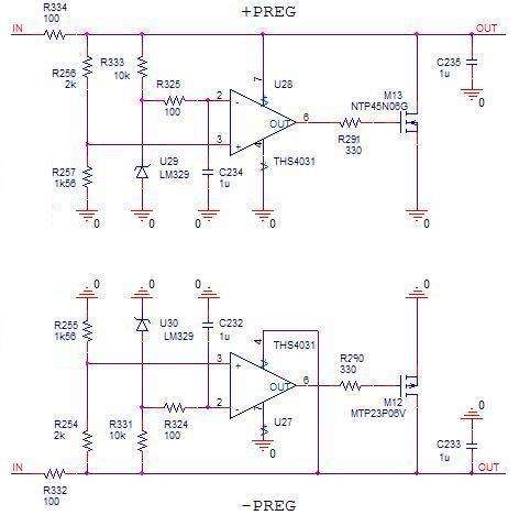
- A new power supply. While the opamps are fed from a standard pair of LM317/LM337 pair of regulators (so no more Jung superregulators), the low noise input stage (while still cascoded) is fed by a pair of onboard parallel regulators. The input stage draws low and almost constant current, so the parallel regulators (on board) can be designed for minimum power dissipation.
- Still zero caps in the signal path.
- Gain
The input followers and the bipolar input gain stage are both running at about 3mA. That's a good trade between low noise and a reasonable input bias current. If the input devices are beta matched, the base currents are cancelling each other and, as a result, the current through the cartridge is minimized. Experimentally, with the Hitachi bipolar pair, I got the current as low as 0.5uA.
Of course, the big question is about the low noise bipolar devices. Which are the best, what can be reasonable used? I have experimented with four complementary pairs:
1) Hitachi 2SC2547/2SA1085
These are the best, but unfortunately, as with other so many great parts, they are now almost extinct. You can still get them, but they are becoming rare and expensive. What makes them unique is not only the low noise, but also the large beta. I was easily able to select a pair with a beta of 400, which is clearly an advantage in terms of input bias current. With these devices, the HPS3.1 head amp noise was 0.28nV/rtHz and the input bias current was 0.5uA.
2) Sanyo 2SC3504/2SA1433
These devices (coming in the extended TO92 case) are part of the Sanyo video devices series. Although not intended for low noise, the FBET polysilicon emitter process is providing extremely good noise performance, at par with the Hitachi pair above. However, beta is not that high; it is difficult to select pairs with a beta over 200. This leads to an input bias current of about 1uA. The noise performance was measured at 0.31nV/rtHz. These devices are in full production at Sanyo and can be purchased through distributors at a very reasonable price.
3) Sanyo 2SC3601/2SA1407
Another FBET pair from Sanyo, in TO126. Consequently, they provide exactly the same noise performance and the same beta, on the low side. I was unable to find any benefit comparing to 2SC3504/2SA1433 above, so this should be an option only if one has these devices at hand. While they are also in full production at Sanyo, this pair is expensive (and 4 pairs are needed).
4) Fairchild KSC3503/KSA1381
A dirt cheap pair from Fairchild, coming in TO126, they cost about $0.6/pair at Mouser. They have very good noise performance (about 0.7nV/rtHz) and decent beta (I was able to easily find pairs with beta 300). With these devices, the noise performance was measured at 0.41nV/rtHz, at par with the best available phono stages available today, while the input bias current was 0.6-0.7uA.
So, pick your poison
The construction is on a single board, the size is about the same as HPS3.1 I'm now looking into building a SMD version. Sanyo is currently manufacturing a FBET device in SMD, but I was so far unable to source it. Otherwise, for top performance, input devices need to be reasonably sorted and matched for beta.
So, which one is better, HPS3.1 or HPS4.0?
From a noise perspective, they are both dead silent, in 97dB efficient horns, ear on grille. From a distortion perspective, HPS4.0 is slightly better, due to a larger loop gain in the head amp. From a RIAA compliance they are identical, provided that 0.5% or better tolerance is provided for the passive devices defining the RIAA response. According to my (sorry, engineer level) ears, they sound identical and wife in the kitchen didn't also comment in any way. More to follow (friends, neighbors, dog, etc...) but at this point I think it's safe to assume they sound pretty much the same. Then, what's left?
Device availability. P channel low noise JFETs from Toshiba are extinct and LSI still has to provide an equivalent (also needs to be validated). Low noise bipolars are readily available, even if they are not intended as such. Of course, there's always the argument of DC through a cartridge as baaaaaaaddddd, but I think that, within reasonable limits, this is just another myth. I can't imagine that each and every supa dupa high end phono stage is nowadays built with low noise JFETs. Either as-is, or by using an input cap, bipolars ought to be used for such low noise applications.
On the flip side, HPS4.0 needs a reasonable level of beta sorting and matching for the input devices. This is for DC purposes only. HPS3.1 doesn't need any kind of sorting, it will work as good with devices out of the tube. However, if you can live with a couple of uA through the MM cartridge, or if you decide for an input cap, then no sorting is required.
Bottom line, HPS4.0 has better noise specs compared to HPS3.1. It should though be noted that this level of performance applies strictly for low impedance MC cartridges. For MM cartridges, the input current noise may contribute significantly, degrading the overall noise performance. But then certainly a MM does not need 0.28nV/rtHz, anything under 1-2nV/rtHz will do just fine, so the complexity of this head amp can barely be justified anyway.
I'll be back ASAP with pictures, measurements, etc... As usual, schematics, Gerbers, measurements will be available on my web site. Meantime, comments are welcomed BTW, for those scared of 0.5uA through the MC cartridge, there's a placeholder for an input cap of your choice
P.S. Voltage supplies are +/-22V, while the parallel regulators are providing +/-15V for the input stage. These voltages are providing the same headroom/dynamic range of 32dB as HPS3.1
For simplicity, I am posting here only the head amp. The rest of gain stages and distributed RIAA correction is identical to HPS3.1, having of course the same performance of +/- 0.1dB.
While the architecture is similar to HPS3.1, there are significant differences:
- Uses only bipolar devices (see the discussion below).
- An emitter follower stage is employed, to provide high input impedance. This stage is coming with a noise penalty, but that's the price that has to be paid.
- Current sources are defining the input stage collector current.
- A new power supply. While the opamps are fed from a standard pair of LM317/LM337 pair of regulators (so no more Jung superregulators), the low noise input stage (while still cascoded) is fed by a pair of onboard parallel regulators. The input stage draws low and almost constant current, so the parallel regulators (on board) can be designed for minimum power dissipation.
- Still zero caps in the signal path.
- Gain
The input followers and the bipolar input gain stage are both running at about 3mA. That's a good trade between low noise and a reasonable input bias current. If the input devices are beta matched, the base currents are cancelling each other and, as a result, the current through the cartridge is minimized. Experimentally, with the Hitachi bipolar pair, I got the current as low as 0.5uA.
Of course, the big question is about the low noise bipolar devices. Which are the best, what can be reasonable used? I have experimented with four complementary pairs:
1) Hitachi 2SC2547/2SA1085
These are the best, but unfortunately, as with other so many great parts, they are now almost extinct. You can still get them, but they are becoming rare and expensive. What makes them unique is not only the low noise, but also the large beta. I was easily able to select a pair with a beta of 400, which is clearly an advantage in terms of input bias current. With these devices, the HPS3.1 head amp noise was 0.28nV/rtHz and the input bias current was 0.5uA.
2) Sanyo 2SC3504/2SA1433
These devices (coming in the extended TO92 case) are part of the Sanyo video devices series. Although not intended for low noise, the FBET polysilicon emitter process is providing extremely good noise performance, at par with the Hitachi pair above. However, beta is not that high; it is difficult to select pairs with a beta over 200. This leads to an input bias current of about 1uA. The noise performance was measured at 0.31nV/rtHz. These devices are in full production at Sanyo and can be purchased through distributors at a very reasonable price.
3) Sanyo 2SC3601/2SA1407
Another FBET pair from Sanyo, in TO126. Consequently, they provide exactly the same noise performance and the same beta, on the low side. I was unable to find any benefit comparing to 2SC3504/2SA1433 above, so this should be an option only if one has these devices at hand. While they are also in full production at Sanyo, this pair is expensive (and 4 pairs are needed).
4) Fairchild KSC3503/KSA1381
A dirt cheap pair from Fairchild, coming in TO126, they cost about $0.6/pair at Mouser. They have very good noise performance (about 0.7nV/rtHz) and decent beta (I was able to easily find pairs with beta 300). With these devices, the noise performance was measured at 0.41nV/rtHz, at par with the best available phono stages available today, while the input bias current was 0.6-0.7uA.
So, pick your poison
The construction is on a single board, the size is about the same as HPS3.1 I'm now looking into building a SMD version. Sanyo is currently manufacturing a FBET device in SMD, but I was so far unable to source it. Otherwise, for top performance, input devices need to be reasonably sorted and matched for beta.
So, which one is better, HPS3.1 or HPS4.0?
From a noise perspective, they are both dead silent, in 97dB efficient horns, ear on grille. From a distortion perspective, HPS4.0 is slightly better, due to a larger loop gain in the head amp. From a RIAA compliance they are identical, provided that 0.5% or better tolerance is provided for the passive devices defining the RIAA response. According to my (sorry, engineer level) ears, they sound identical and wife in the kitchen didn't also comment in any way. More to follow (friends, neighbors, dog, etc...) but at this point I think it's safe to assume they sound pretty much the same. Then, what's left?
Device availability. P channel low noise JFETs from Toshiba are extinct and LSI still has to provide an equivalent (also needs to be validated). Low noise bipolars are readily available, even if they are not intended as such. Of course, there's always the argument of DC through a cartridge as baaaaaaaddddd, but I think that, within reasonable limits, this is just another myth. I can't imagine that each and every supa dupa high end phono stage is nowadays built with low noise JFETs. Either as-is, or by using an input cap, bipolars ought to be used for such low noise applications.
On the flip side, HPS4.0 needs a reasonable level of beta sorting and matching for the input devices. This is for DC purposes only. HPS3.1 doesn't need any kind of sorting, it will work as good with devices out of the tube. However, if you can live with a couple of uA through the MM cartridge, or if you decide for an input cap, then no sorting is required.
Bottom line, HPS4.0 has better noise specs compared to HPS3.1. It should though be noted that this level of performance applies strictly for low impedance MC cartridges. For MM cartridges, the input current noise may contribute significantly, degrading the overall noise performance. But then certainly a MM does not need 0.28nV/rtHz, anything under 1-2nV/rtHz will do just fine, so the complexity of this head amp can barely be justified anyway.
I'll be back ASAP with pictures, measurements, etc... As usual, schematics, Gerbers, measurements will be available on my web site. Meantime, comments are welcomed
BTW, for those scared of 0.5uA through the MC cartridge, there's a placeholder for an input cap of your choice
P.S. Voltage supplies are +/-22V, while the parallel regulators are providing +/-15V for the input stage. These voltages are providing the same headroom/dynamic range of 32dB as HPS3.1
Last edited:
Congratulations to yet another great iteration of your design! Leaves me still ashamed that my power amp is still unfinished while you iterate happily.
Only thing that seems missing for world wide cloning is the option to hook up either MM or MC (switchable gain?).
Have fun, Hannes
Only thing that seems missing for world wide cloning is the option to hook up either MM or MC (switchable gain?).
Have fun, Hannes
Congratulations to yet another great iteration of your design! Leaves me still ashamed that my power amp is still unfinished while you iterate happily.
Only thing that seems missing for world wide cloning is the option to hook up either MM or MC (switchable gain?).
Have fun, Hannes
This is not for MM at all... The input current noise will significantly degrade the noise performance. OTOH, you don't need 0.28nV/rtHz for MM so there's really no incentive to build this phono stage.
As regards the Hitachi 2SC2547/2SA1085, Radionics sell a 'Magnatec' version. Are these the same or just a bad copy? I have never heard of Magnatec myself and Radionics have no spec sheets either?
Magnatec | Semiconductors | Discretes | Bipolar Transistors | NPN Small Signal |2SC2547E
and
Magnatec | Semiconductors | Discretes | Bipolar Transistors | PNP Small Signal |2SA1085E
Magnatec | Semiconductors | Discretes | Bipolar Transistors | NPN Small Signal |2SC2547E
and
Magnatec | Semiconductors | Discretes | Bipolar Transistors | PNP Small Signal |2SA1085E
As regards the Hitachi 2SC2547/2SA1085, Radionics sell a 'Magnatec' version. Are these the same or just a bad copy? I have never heard of Magnatec myself and Radionics have no spec sheets either?
Magnatec | Semiconductors | Discretes | Bipolar Transistors | NPN Small Signal |2SC2547E
and
Magnatec | Semiconductors | Discretes | Bipolar Transistors | PNP Small Signal |2SA1085E
Don't know what to say, but if they are not genuine Hitachi I wouldn't touch them with a pole.
I was offered these devices from Dalbani in the UK, but then I decided I have already enough for my life expectancy
. They still have them in stock. But then these parts are sooner or later going to dissapear anyway, so if I would have to choose between these and the Toshiba JFETs, I'll go for Toshiba.Just curious. Why did you rule out the Fairchild KSA992/KSC1845 pair. I know you are aware of these devices and that are cheap and available and have fairly high beta. I'm sure you had a reason. What are the shortcomings of this pair?
Like many other so-called "low noise" devices (including 2SC2240/2SA970) they have Rbb~40ohm. That's an order of magnitude worse than what is required here.
Thanks. That, like much other information, isn't given on many spec sheets.
You can always do some (more or less) precise calclations based on the iso-NF curves in the datasheet. However, you can tell if the device is low noise at a glance. If the iso-NF curves are not specified towards low source impedances (10-100 ohm) then that device has high Rbb and consequently high noise (for a MC phono stage).
Syn08, any thoughts on the THAT matched pairs, or the MAT series devices in place of the types you used in your head amp?
For MAT02 (NPN) and MAT03 (PNP) I have measured Rbb at about 25ohm (slightly lower for MAT03), being in between the really low noise Hitachi and Sanyo FBET pairs and the 40ohm typical for "low noise" diffused devices. The big problem is the PNP beta. It doesn't go over 150, and that makes matching with the NPN counterpart very difficult, in particular if you look at the $25 price tag
. But of course, if you are happy with a few microamps through the MC cartridge, and an overall 0.6-0.7nV/rtHz noise performance, they are pretty good.THAT devices have about the same noise/Rbb as the AD parts, but beta (in particular for the PNP part) is very low: under 100. They are also significantly more expensive than the Sanyo FBET parts, not to mention the Fairchild.
The only advantage that I can think of is that these monolithic duals could probably be paralleled without balance resistors (saving a little noise), but I haven't tried this.
Last edited:
Great work !
Me being more of a bipolar guy really enjoy that circuit.
Your knowlage of active devices is quite staggering.
By the way THAT can make your own transistor if you buy 500-1000 pc.
My friend Jürgen Ultee has designed a phonoamp for Van den Hul with THAT transistors made to his spec. It is an interesting design with inductive equalization.
He is a trained HF engineer and knows a lot about inductors and layout.
Great work !
Me being more of a bipolar guy really enjoy that circuit.
Glad you like it.
Actually, it's a more difficult and demanding construction compared to the HPS 3.1, already on my web site. This design should be considered more like a backup plan, in case one is unable to find the Toshiba JFETs (now or in the future). It has better noise performances, but at those levels HPS 3.1 is already good enough, for the most demanding ears, anyway.
Syn08, you have proably addressed these questions elsewhere, so if they are repeats, please accept my apologies in advance.
On the HPS3, you use a balanced/symmetrical JFET input that drives folded cascode type VAS stage. What are your thoughts on a straight diff amp input (maybe with multiple devices in parallel to improve the noise performance). This would drive a folded cascode, or a mirror arrangement and then onto the op-amp based second stage. Is the noise performance of this balanced stage better than a classic long tail pair (again, we are talking JFET here). I have to admit, the classic long tail would have been my 1st cut approach, especially since the PSSR of a long tail pair is better than a folded cascode arrangement.
BTW, I have partially built up a phono amp design based on Dennis Colins AX design, I've changed some of the values (notably lower resistor values and higher cap values) and used LM4562's. I have yet to finish it off - hope to do so in the next few weeks.
Syn08, you have proably addressed these questions elsewhere, so if they are repeats, please accept my apologies in advance.
On the HPS3, you use a balanced/symmetrical JFET input that drives folded cascode type VAS stage. What are your thoughts on a straight diff amp input (maybe with multiple devices in parallel to improve the noise performance). This would drive a folded cascode, or a mirror arrangement and then onto the op-amp based second stage. Is the noise performance of this balanced stage better than a classic long tail pair (again, we are talking JFET here). I have to admit, the classic long tail would have been my 1st cut approach, especially since the PSSR of a long tail pair is better than a folded cascode arrangement.
Unfortunately, differential stages come with a 3dB penalty in noise. So, you need four devices in differential configuration to get the same noise as one device in single ended configuration. To add insult to injury, building an ultra low noise current source to feed a LTP is a problem by itself. True, it's noise is common mode, but will appear at the output due to the inherent finite CMRR.
"Unfortunately, differential stages come with a 3dB penalty in noise."
but does the balanced input stage also not suffer the same fate? Seems we cannot have our cake and eat it. Anything other than a single ended has a noise penalty . . . but we know a single ended solution is also not ideal.
but does the balanced input stage also not suffer the same fate? Seems we cannot have our cake and eat it. Anything other than a single ended has a noise penalty . . . but we know a single ended solution is also not ideal.
Great circuit and very well selected components, Syn.
I will try to build a very low noise preamp as this, and i have bought for this purpose some 2SC2545/2SA1083, 2SC2547E/2SA1085E.
My doubt are related how what type of input devices topology: emitter follower or base grounded topology?
Have you compared the two configurations or at least can you tell me because you have choiced the follower circuit for the first stage?
Which advantages?
Thanks in advance, Francesco.
Last edited:
"Unfortunately, differential stages come with a 3dB penalty in noise."
but does the balanced input stage also not suffer the same fate? Seems we cannot have our cake and eat it. Anything other than a single ended has a noise penalty . . . but we know a single ended solution is also not ideal.
"To add insult to injury, building an ultra low noise current source to feed a LTP is a problem by itself. "
Howland current pump might be the answer here using low noise op-amps.
Haven't looked closely, but on top of my head I think a balanced configuration will not come with a noise penalty, however I wouldn't know how to apply the headamp feedback loop.
The Howland current pump noise is anything but low, and it's not about the opamp noise, but about the matched resistors network.
Yes, the single ended configuration is not ideal but, from a noise perspective, it's still the best.
Great circuit and very well selected components, Syn.
I will try to build a very low noise preamp as this, and i have bought for this purpose some 2SC2545/2SA1083, 2SC2547E/2SA1085E.
My doubt are related how what type of input devices topology: emitter follower or base grounded topology?
Have you compared the two configurations or at least can you tell me because you have choiced the follower circuit for the first stage?
Which advantages?
Thanks in advance, Francesco.
Francesco,
From a noise perspective, it would be about the same. However, you won't be able to get a high impedance input with a common base circuit. If this is not important for you, then certainly the common base circuit has some advantages.
Actually one idea that I am further contemplating is a floating input stage, similar to prof. Leach circuit. I would certainly use common base in such a circuit. The big advantage of a floating configuration is that you can get zero MC cartridge current, even with unmatched bipolars, since the MC cartridge is not referred to ground. It's not that simple, though
- Status
- This old topic is closed. If you want to reopen this topic, contact a moderator using the "Report Post" button.
- Home
- Source & Line
- Analogue Source
- HPS 4.0 phono stage