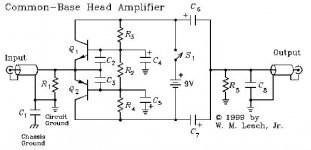
For certain phono cartridges, the common base stage has certain advantages. It IS linear, and it can be very quiet. However, it loads the cartridge, significantly, and many MC cartridges don't sound as good loaded this way.
This is why the JC-1 DC, and its bigger brother, the JC-1 AC actually failed to be as popular as I had hoped. I modified a JC-1 AC to be either inverting (Hi Z) or non-inverting (Low Z) with a switch. Making A-B comparisons, we found that, in general, the (Hi Z) position sounded best. This meant that the common base connection actually compromised the sound, somewhat. This was especially true with the JC-1, either AC or DC, because the parallel common base connection, halved the effective input impedance, for a given operating current. However, with a 'starved' Iq, the input impedance would increase, perhaps high enough to sound optimum, but it would be more noisy, to be sure.
This is why the JC-1 DC, and its bigger brother, the JC-1 AC actually failed to be as popular as I had hoped. I modified a JC-1 AC to be either inverting (Hi Z) or non-inverting (Low Z) with a switch. Making A-B comparisons, we found that, in general, the (Hi Z) position sounded best. This meant that the common base connection actually compromised the sound, somewhat. This was especially true with the JC-1, either AC or DC, because the parallel common base connection, halved the effective input impedance, for a given operating current. However, with a 'starved' Iq, the input impedance would increase, perhaps high enough to sound optimum, but it would be more noisy, to be sure.
John,
impedance matching can have a considerable impact on the sound. I don`t believe for a minute that, for instance, the lowest Rin would give the best results in a certain (if any) case. Preferably, adjustments should be made to the specific characteristic of each cartridge, trying different bias currents or in other ways.
impedance matching can have a considerable impact on the sound. I don`t believe for a minute that, for instance, the lowest Rin would give the best results in a certain (if any) case. Preferably, adjustments should be made to the specific characteristic of each cartridge, trying different bias currents or in other ways.
I might qualify this with what I know about Dr. Van den Hul, as I know him, and have heard him speak about cartridge loading. His take is that cartridges like to be 'shorted' rather than 'bridged' i.e. 47K for various reasons. It is quite possible that his phono cartridges are designed to favor a 'shorted' load. I used to think the same thing once, but I found, with a number of other cartridges, that 'shorting' in input appeared to 'over-damp' the cartridge and make it sound like it was 'underwater'. That is why I went away from the dual common bass input design that became the JC-1, AC or DC.
The original JC-1 had a Variable loading that seemed to OK at the time. It even had the advantage of reducing the output of higher resistance cartridges and this tended to track the actual output of the cartridges themselves, so it kept the pre-preamp from overloading.
In 1978, Ortofon, introduced essentially the JC-1 DC design themselves using the 2N4401-4403 combination, themselves. Apparently, they could find no better substitute for them at the time. I am not surprised.
Great work !
Me being more of a bipolar guy really enjoy that circuit.
Your knowlage of active devices is quite staggering.
By the way THAT can make your own transistor if you buy 500-1000 pc.
My friend Jürgen Ultee has designed a phonoamp for Van den Hul with THAT transistors made to his spec. It is an interesting design with inductive equalization.
He is a trained HF engineer and knows a lot about inductors and layout.
Sorry John, he has hired the german designer above,
Reinhard
you will be surprised that there is a van den hul phono stage on the way that a friend of mine designed with a bipolar COMMON BASE stage
maybe it has a twist, clever guy he is the RIAA is done ONLY with coils
Each and every frequency dependent network needs two components,
Reinhard
I might qualify this with what I know about Dr. Van den Hul, as I know him, and have heard him speak about cartridge loading. His take is that cartridges like to be 'shorted' rather than 'bridged' i.e. 47K for various reasons. It is quite possible that his phono cartridges are designed to favor a 'shorted' load. I used to think the same thing once, but I found, with a number of other cartridges, that 'shorting' in input appeared to 'over-damp' the cartridge and make it sound like it was 'underwater'. That is why I went away from the dual common bass input design that became the JC-1, AC or DC.
The original JC-1 had a Variable loading that seemed to OK at the time. It even had the advantage of reducing the output of higher resistance cartridges and this tended to track the actual output of the cartridges themselves, so it kept the pre-preamp from overloading.
In 1978, Ortofon, introduced essentially the JC-1 DC design themselves using the 2N4401-4403 combination, themselves. Apparently, they could find no better substitute for them at the time. I am not surprised.
At last weekend I have compare the JC-1 and the Lehmann phono cube MC input by a customer.
krishu.de » Lehmann Clone
The JC-1 operates as "common base" and the SSM2017 from Lehman phono cube as "common emitter"
For use the JC1 I it must to be select MM-input at the Lehmann phono cube with 47 K input impedance.
I have tested the "Art 1" (Art1, Art ONE, audio technica) as very low internal impedance and the "CarnegieTWO", successor from this one:
http://www.zenn.com.sg/Madrigal_Carnegie_One__used.JPG
from Madrigal as higher internal impedance arround 50 ohms
And the result was just as I predicted: The "CarnegieTWO" sounded clearly better without JC1 as "MC head amp" (in the MC position at Lehman with arround 3K termination load)
But the "Art 1" sounded very bad without JC1 as "MC head amp", even by choice of a very low termination load below 12 ohms, i. e., the JC1 is nessecary by the "Art 1"
By an another customer, that uses also different top cartridges from Lyra and Benz-Micro (Titan/Ebony S), same sonic differences to be observed, perhaps because the Madrigal Carnegie and the Benz Micro are very similar (also the "Art 1" and the "Titan"). Instead of Lehmann he use a diy version with MAT03 dual transistor differential input amp and instead of JC-1 a diy version of Hiraga's prepre (current mirror with 2SC1775 and a very large power supply). But the same two different basic circuits
For me this gives only one conclusion: By high class commercial and diy MM/MC RIAA head amps there must be present (in all cases) both basic internal circuit variants for MC: common base and common emitter - in addition to the already mostly existing termination resistor input network !!!
But for me the actually question is follow: why I don't get high sonic transmission by cartridges with low internal resistance (like the above mentioned) at a common emitter input circuit, even, if I select external low termination resistance value around 5 ohms until 20 ohms?
New for me is the use of an emitter follower stage as input for phono (as mentioned by start of this thread. This topology I have never heard and tested in real live, because I don't know commercial phono pre amplifier brands with such input stage.
Last edited:
It's OK that VDH is using another design, and designer. I just thought that he might as well 'rip off' my old design, as Ortofon did, 30 years go. For the record, I am now in charge of 3 separate phono stages, one for Parasound, one for me, and one for someone else. I don't use common base input, any more, but your listening opinions are interesting, in regards to it. Perhaps, a short feedback loop would be a better solution to the low Z requirement.
lr riaa
it`s posible to design a riaa without capacitors. ok....resistors are needed too.
A "No C" RIAA Preamp
it`s posible to design a riaa without capacitors. ok....resistors are needed too.
A "No C" RIAA Preamp
Perhaps, a short feedback loop would be a better solution to the low Z requirement.
Now, John. After bashing about feedback loops in phono preamps, now you are planning to rip off my designs and use yourself a negative feedback loop? That's not fair

it`s posible to design a riaa without capacitors. ok....resistors are needed too.
A "No C" RIAA Preamp
My HPS 3.1 and 4.0 RIAA don't have any caps in the signal path. Also no signal transformers
it`s posible to design a riaa without capacitors. ok....resistors are needed too.
A "No C" RIAA Preamp
As I told, two components
it`s posible to design a riaa without capacitors. ok....resistors are needed too.
A "No C" RIAA Preamp
#155, John Curl: Interesting design. I also realize that VDH would probably supply the wire for the inductors, as this is important. Caps have many problems.
Riaa networks with only inductors are new for me. But I have heard about RIAA network designs, both with capacitors and inductors. As I know, there are the advantage of a not complex load for the voltage gain stage before network. But I don't know, if this a real advantage or only a cosmetic advantage? Are additional advantages known (perhaps more exactly equalizing - e. g.)?
here some weblinks:
http://digilander.libero.it/paeng/inductive_riaa.htm (TANGO EQ-600P)
http://www.webalice.it/ansa_ht/uv638jed4/f_Arw/EQ-2L_Tango(1).jpg (Schaltplan TANGO EQ-600P)
passive RIAA LCR unit
http://www.intactaudio.com/forum/files/picture_13_153.png
RIAA-Entzerrung mit Spulen - Inductive RIAA deemphasis Networks - Phono - allgemein - Analog-Forum
Caps have many problems - please let us know more exactly, what problems by caps you have identified.
I found, the best possible cap versions are large snubber versions with high voltages and high weight, e. g. Arcotronics C44BPF13220ZB0J (datasheet www.arcotronics.com/download/power.php?id=8).
But I would be surpriced, if inductors (air coils) don't have many problems. I haven't experience with coils for RIAA, but I suppose, that coils are much more sensitive to magnetic interferences from unwanted outside sources. It would take at least an inductor encapsulation in a mu metal enclosure (housing) - so I guess.
Last edited:
I would like to mention Hawksford preamp and Leach preamp
Attachments
Last edited:
- Status
- This old topic is closed. If you want to reopen this topic, contact a moderator using the "Report Post" button.
- Home
- Source & Line
- Analogue Source
- HPS 4.0 phono stage