For pure current injection the feedback node has to float and be independent from voltage, This is the very reason I advocate current sources and not something where the current is set by transistors. If you use resistors as current set, you change the working parameters with the signal. for me voltage feedback is always through a high impedance node, where you use a device for the voltage feedback.
Current feedback is not to be mixed up with a current output Amp... the latter will not work with most speakers, as it will take out impedance rise of the cross-over, one notably exception is my speakers from Raidho, as our x-over is founded in current diversion.
Current feedback is not to be mixed up with a current output Amp... the latter will not work with most speakers, as it will take out impedance rise of the cross-over, one notably exception is my speakers from Raidho, as our x-over is founded in current diversion.
Last edited:
As i said, for me it does not matter if current or voltage or power is injected to define if it is VFB or CFB. I learned formally that the diffenrence is in the open loop gain and related bandwidth. Simplified one could say :
VFB : high gain, low open loop bandwidth
CFB : lower gain, high open loop bandwidth
A figure of merit after Bob Cordell could be Gain x Bandwidth @ 20kHz.
It is also not true that CFB always makes a faster amp.
VFB amps can be made very fast if driving the input stgae into class AB is alowed ( provided ). Stochino made some damn fast VFB amps in the 90th.
The ultimate figure of merit for speed is Gain x Bandwidth provided the amp can be made stable with the same gain.
For me its not a quest of one being superior over the other, just to distinguish the two from each other, though it's not a case of black and white, but more like different shades of grey.
When that is said, for large signals I do have a tendency to make my designs more CFb than VFb. Mostly because i like it better when the signal and the feedback shares as much if the circuitry as possible, that is most often compromised in VFb designs, where you need an extra device for injecting the feedback.
When that is said, for large signals I do have a tendency to make my designs more CFb than VFb. Mostly because i like it better when the signal and the feedback shares as much if the circuitry as possible, that is most often compromised in VFb designs, where you need an extra device for injecting the feedback.
Some theoreticians even went so far that a CFB amp does not exist and that it is a flawed VFB amp at best.
I'm following this too, and currently am thinking like in the above statement, after long thinking about it, my point of view (at this moment, and may change yet) is that all amps are sort of VFB but with a CFB flavor. But like you Joachim I keep following the thread. And I will try not to say to much, I'm ignored anyway
")
Last edited:
I think the best way to define a current feedback amp may simply be that the feedback transistor is in common-base configuration. That is the most significant difference, no? It's mostly the input stage topology that allows CFB amps to benefit in many ways.
It helps to understand that engineers or hobbyists without a special interest in math probably won't realize that the relationship between current and voltage is purely symmetrical. I see current and voltage as the same thing; they are what occur when you divide power. If there is one but not the other then there is no power; so even if such a thing occurred no one could ever measure it. Early on it was established that voltage was to be the independent variable and current the resulting variable, but this has nothing to do with reality, it is just a convention which allowed massive amounts of textbooks to be printed with simple math that would allow someone to learn electronics and service equipment without a complete understanding.
If a CFB amp were designed with perfect devices, it would be no different than an equivalent VFB amp designed from perfect devices. So then the important difference must be the devices used, and apparently CFB results in a topology which allows transistors to make an amp which is better in certain ways.
I think the CFB/VFB issue reveals to us the depth of the misconceptions in the DIY Audio community WRT what things determine the performance of an amplifier.
Last edited:
I think, we are think alike here. Tell me if not so
Yes true (about the common base configuration). But then we are not connecting the output signal of the amplifier directly to that common-base circuit (E or C), we are going to use an resistor in there (somewhere). This makes it into a special kind of VFB, as I said a VFB with a CFB flavor.
Yes
Yes, a CFB is a flavor (special form/topology) of an VFB.
Yes, and it is not getting any better (reading current ongoing discussions).
I think the best way to define a current feedback amp may simply be that the feedback transistor is in common-base configuration. That is the most significant difference, no? It's mostly the input stage topology that allows CFB amps to benefit in many ways.
Yes true (about the common base configuration). But then we are not connecting the output signal of the amplifier directly to that common-base circuit (E or C), we are going to use an resistor in there (somewhere). This makes it into a special kind of VFB, as I said a VFB with a CFB flavor.
It helps to understand that engineers or hobbyists without a special interest in math probably won't realize that the relationship between current and voltage is purely symmetrical. I see current and voltage as the same thing; they are what occur when you divide power. If there is one but not the other then there is no power; so even if such a thing occurred no one could ever measure it. Early on it was established that voltage was to be the independent variable and current the resulting variable, but this has nothing to do with reality, it is just a convention which allowed massive amounts of textbooks to be printed with simple math that would allow someone to learn electronics and service equipment without a complete understanding.
Yes
If a CFB amp were designed with perfect devices, it would be no different than an equivalent VFB amp designed from perfect devices. So then the important difference must be the devices used, and apparently CFB results in a topology which allows transistors to make an amp which is better in certain ways.
Yes, a CFB is a flavor (special form/topology) of an VFB.
I think the CFB/VFB issue reveals to us the depth of the misconceptions in the DIY Audio community WRT which modifications will improve performance and which ones won't.
Yes, and it is not getting any better (reading current ongoing discussions
).
Last edited:
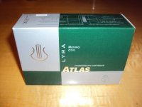
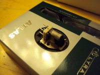
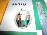
I have a new toy, a Lyra Atlas.
I have heard this piece of art in many systems and have used it on shows but this is the first time i have it at home.
I will mount it tonight and i am very excited.
I have heard this piece of art in many systems and have used it on shows but this is the first time i have it at home.
I will mount it tonight and i am very excited.
Attachments

I have a new toy, a Lyra Atlas.
I have heard this piece of art in many systems and have used it on shows but this is the first time i have it at home.
I will mount it tonight and i am very excited.
Wow nice toy. I just received my Dynavector DV-1s which will be loaded by 200R on Paradise R3.
After getting Peak Atlas now a Lyra Atlas. Joachim is on Hesiod's trail for achieving a primordial Titan's world class sound.
An externally hosted image should be here but it was not working when we last tested it.