Do you remember FS´s phono i build him ? There you substituted a split supply with a single supply and it worked to my horror nevertheless.
That was the hat trick the other way around. The dove mutated into a cylinder.
This worked fine because you had a valid signal and supply ground scheme - floating
with single supply, but nevertheless at center because of equal supply currents ..
Will prepare dinner now.
I am a genius and i do not know it ! What a blessing.
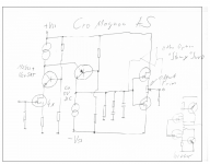
Here is AS idea. It may have some small flaws but in general it should work.
Input stage could be referenced to negative supply too ?
I kept the cascoding of the J-Fets because that lowers gate current and noise. Also lowers input capacitance although with MC cartridge low impedance drive that may not be necesarry. Totally DC coupled.
Will eat some soup too and then listen to my new line stage, horror of horrors WITH CD !
Attachments
I am a genius and i do not know it ! What a blessing.
Here is AS idea. It may have some small flaws but in general it should work.
Input stage could be referenced to negative supply too ?
I kept the cascoding of the J-Fets because that lowers gate current and noise. Also lowers input capacitance although with MC cartridge low impedance drive that may not be necesarry. Totally DC coupled.
Will eat some soup too and then listen to my new line stage, horror of horrors WITH CD !
ok this is a hat off of a circuit. I really like it.
Looking at first glance it is non-inverting, has enough gain and it should be more stable offset wise than the other one and also can be completely DC coupled.
Very interesting indeed.
I will pass into simulation and try to see if capacitors from paradise (for the groupbuy we are ghaving now of the V-CAP) can be use here as well.
And for what it is worth, this has a 'simulated' gain of just over 74dB.
yeah still not enough. in practice you will have gain losses and also to get 61-62dB you will need about 80dB.
It looks like the latest approach is way better.
I have to check noise however as it might be noisier than our target!
Days of miracles and wonders....Frank Sinatra It Never Entered My Mind. - YouTube
I am a genius and i do not know it ! What a blessing.
Here is AS idea. It may have some small flaws but in general it should work.
Input stage could be referenced to negative supply too ?
I kept the cascoding of the J-Fets because that lowers gate current and noise. Also lowers input capacitance although with MC cartridge low impedance drive that may not be necesarry. Totally DC coupled.
Will eat some soup too and then listen to my new line stage, horror of horrors WITH CD !
The npn cascode transistor is not required from an input capacitance point of view.
If you want low Vds on the Jfet it should work with the pnp alone also.
A servo will be required due to high gain and drift.
The "first" current source has to carry twice the current of the second one.
The npn cascode transistor is not required from an input capacitance point of view.
If you want low Vds on the Jfet it should work with the pnp alone also.
A servo will be required due to high gain and drift.
The "first" current source has to carry twice the current of the second one.
well if you use a pair of IF3601 I bet you can get as much transconductance out of the pair with probably 10mA tot vs the 40mA of the 4 SK170!!
Can't wait for the new batch to come out....
Your circuit idea drawn up comes soon. It is immensely workable. Hats off.
.. and wallet open please ..
No, nobody will pay me for that cause I am not a highly paid Electrical Engineer .
Indeed it's an old hat as we say, remember our examination in "Impulstechnik" in
Paderborn (Prof. Nowack from Bochum) some 30 years ago. Evaluation of a circuit
like that in your post 8063
http://www.diyaudio.com/forums/analogue-source/154210-mpp-807.html#post3280769
without the npn was part of the questions. Nothing new under the sun.
Last edited:
")
That study in Paderborn was "Hard Bread" as we say here. Somehow in the back of my mind it must have being ringing a bell.
I am pretty sure I only remember this exam question, because I did not see the cascode at the time and was consequently downgraded. And so my long folded cascode journey started.
Of cause the PNP BJT in the folded cascode has the same purpose of reducing the input capacitance of the J-Fet array BUT with the additional series cascode we can run the J-Fets
on lower voltage, that reduces gate current plus heating and that reduces noise. We also can run that cascode on quite high voltage ( provided we are under the avalanche voltage of the BJT that is another source of noise ) so we have more dynamic range.
I am undecided on this .
on lower voltage, that reduces gate current plus heating and that reduces noise. We also can run that cascode on quite high voltage ( provided we are under the avalanche voltage of the BJT that is another source of noise ) so we have more dynamic range.
I am undecided on this .
ok I have spectacular news for everybody.
I modeled the circuit, we can get the required gain (hopefully same applied in practice).
Also same exact capacitors and value for the RIAA I gave away in these pages can be used to have same exact precision had on Paradise.
Noise wise we are on the good side.
so now the circuit looks very, very promising which means that all the people who took part to the GB will be able to use the same capacitors to build this one too.
EDIT: Output is still out of phase with the input, which is still not a big deal anyway, but I jsut wanted to correct my previous statement.
Last edited:
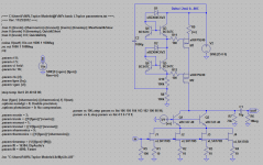
and here is the circuit for the joy of everybody.
Unfortunately I won't be able to do much work in the next days as I want want to work on the new linestage design I am helping out with a very regarded user if this forum.
I like to work on both but unfortunately it is impossible...so here is my contribute for now.
Here we go fully simulated and apparantely working (The resistors still need tweaking to get absolute precision)