I have some concerns about the gain i am getting. If i have not wired something wrong it seems too low.
The gain strongly depends on the gain introduced by then CCS.
If I am not wrong that arrangement should not boost more than 50db or so
This is just my guess and I am going to run simulation tomorrow and post results.
The dc offset can't be evaluated until the circuit provides about 80dB.
Accordingly to my simulation you only need 4 k170 with no feedback resistor and a resistor of about 270Kohm to obtain proper gain.
However I have noticed that with BJT current sources the input impedance doesn't reach high enough value to have a reasonable current riaa.
However them CCS I drew allows proper functionality.
Today. Was too lazy..I had dentist and then I didn't get a chance to work on the CCS.
Beside I am also really engaged working on a new line stage with a very regarded designer of this community which name shall remain anonymous
") and I am ideally behind with that too!!! Ahhhh so many things I would like to do so little time I can and want to do them.
and I am ideally behind with that too!!! Ahhhh so many things I would like to do so little time I can and want to do them.Please keep us informed on your findings with the CCS and e gain on the circuit.
Thanks for all your efforts.
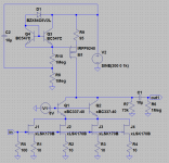
Here another CCS.
After some experimentation I got this (see attachment) it has a very slight negative temperature coefficient and seems to be really stable.
Varying the load from 1 to 100 ohm gives only a delta of 2.7 uA on the 26mA output current, that is about 1ppm.
As it is running at a good current it will get warm and thus the negative temperature coefficient will help stabilize it.
The zener diode can be replace by a string (3 or 4) of led’s. And a capacitor could be added parallel to Q3(ec), this will remove some noise. I do not know what the overall noise figure of this circuit is.
[Edit] P.s. it runs (in the schema) at/from 200V, but that is not needed the collectors of Q1 and Q2 are (in the schema) at about 7 Volt.
[Edit] P.s. it will be needed to replace the 1Meg resistors with 100K resistors when running from a more realistic voltage.
Attachments
Last edited:
So you are really using a big P-Channel one. I should have some.
Have you calculated the gain of this circuit ?
No success on my side so far. I get the DC drift super stable but i end up with too low gain. Of cause the low gain relaxes the demand on the CCS.
As the current in the 170's is very critical it is difficult to get a realistic figure for gain and noise (and this is not my field of expertise you know
). Maybe the easiest way is just to build it (it's not very complex).See it as just one of Frans’s doodle’s
I will use 3 x green Leds. Are they not running on very low current ?
It may work though. Can use a zener instead.
Yes, they are running on 'ultra'-low current, no light will be visible
After some experimentation I got this (see attachment) it has a very slight negative temperature coefficient and seems to be really stable.
Varying the load from 1 to 100 ohm gives only a delta of 2.7 uA on the 26mA output current, that is about 1ppm.
As it is running at a good current it will get warm and thus the negative temperature coefficient will help stabilize it.
The zener diode can be replace by a string (3 or 4) of led’s. And a capacitor could be added parallel to Q3(ec), this will remove some noise. I do not know what the overall noise figure of this circuit is.
[Edit] P.s. it runs (in the schema) at/from 200V, but that is not needed the collectors of Q1 and Q2 are (in the schema) at about 7 Volt.
[Edit] P.s. it will be needed to replace the 1Meg resistors with 100K resistors when running from a more realistic voltage.
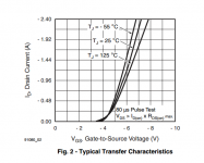
Some research gives the attached graph (for the IRF9610) it shows that Vgs is independent of temperature for about 100mA Id; for the IRFP240 this is at 4.8V at 300mA (about). Somewhere there should be a fit for 30mA (as is needed here).
Attachments
Some research gives the attached graph (for the IRF9610) it shows that Vgs is independent of temperature for about 100mA Id; for the IRFP240 this is at 4.8V at 300mA (about). Somewhere there should be a fit for 30mA (as is needed here).
Or, it should be possible to match a DZtc to the DMOStc and get a temperature neutral system with only a zener and a mosfet
No need for the 2 transistors (but keep the resistors and the cap).Some research gives the attached graph (for the IRF9610) it shows that Vgs is independent of temperature for about 100mA Id; for the IRFP240 this is at 4.8V at 300mA (about). Somewhere there should be a fit for 30mA (as is needed here).
Take a look at the 3LP01M
http://www.onsemi.com/pub_link/Collateral/3LP01M-D.PDF
---Gary
Almost
now if only that was at 2.7V (there the zener is also about Tc neutral).And I found this http://www.cse.psu.edu/~kyusun/class/cse577/11s/lec/S05BiasCkt.pdf it has lots of information about self biasing.
this is a very good one!
this is a very good one!
It will not work for the purpose, due to the small SOA and 150mW maximum dissipation. At 30mA and Vcc 35V the device to be used must be able to dissipate at the least 20 * 30m = 600mW (and that is not even considering any margin/SOA concerns).
It will not work for the purpose, due to the small SOA and 150mW maximum dissipation. At 30mA and Vcc 35V the device to be used must be able to dissipate at the least 20 * 30m = 600mW (and that is not even considering any margin/SOA concerns).
true! too bad!
I still think that the IRF960 cascoded with the OP-AMP looped should be implemented and tested as it could be a very nice working solution.
Beside just as a thought aside, matchying the CCs for TempCo against the CS input stage might be pain as this might mean that in order to have minimum drift you might want to adjust current flowing through the input stage and thus changing gain and might make it really hard to build one matched 60-61dB matched stereo unit.
At the end it is obviously the most refined solution IMHO but it might be nearly impossible or really impracticle just my two cents.
At the end it is obviously the most refined solution IMHO but it might be nearly impossible or really impracticle just my two cents.