Hi Sampler
Can you post a file with the values you got in your sim ?
I need to find input stage output imp at 1kHz
Does your sim give the output imp with the riaa filter connected ?
Can you plot this impedance without the riaa filter connected ?
Hi Ricardo,
This is output impedance without anything connected to output, so it's about 1.3M parallel to shunting resistor 130k in Joachims schematics.
Sampler, i use more or less the same input structure in my tube RIAA and it works.
For Ulf, i will show you the Transcendent RIAA. The input tubes in mine are aranged the same way.
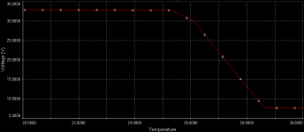
But 1 tube is not the same piece of cake as 3 BF862 running near Ids with just ~20V to bias properly. I'm sure it will work, just getting to stable dc op point will be quite nontrivial. Here is a temperature sweep of whole circuit vs. output voltage, take it with a grain of salt but the picture is clear.
I think I saw a thread couple years ago were very similar concept was discussed in great detail, where is that search button...
Edit: Found it Great stuff with lot's of guru's
")
Attachments
Last edited:
Ok, here is what my simulator spitted out. Gain is 57dB and good riaa compliance with increased shunting resistor from 130k to 142k. Typical nice SE harmonic distribution for 1Vrms out with H2 dominant. There was missing bias resistor for buffer, added that.
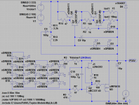
Just to let you(all) know that I like it, here a fitting PSU
Attachments
Last edited:
Just to let you(all) know that I like it, here a fitting PSU
All LED's running at 1.2mA, so it can be used as the light source of the cave
Just to let you(all) know that I like it, here a fitting PSU
Hi Frans
How much current can it deliver ?
Would you care to describe the circuit functioning for us in human language ?
Hi Frans
How much current can it deliver ?
Would you care to describe the circuit functioning for us in human language ?
From the circuit as shown I estimated the 40mA was plenty, the CCS is running at 86mA (and if 40mA is indeed plenty it could be lowered to 60mA). In general I like the CCS at 1.5 to 2 times the current needed by the attached appliance (in this case the CroMagnon). The CCS can be adjusted by changing the 15 Ohm's resistor.
The short description is:
1) Q6/Q7 form a constant voltage source, the reference voltage for this is V(out) + V(D5) + V(D3).
2) Q1/Q3 form a constant current source, the current set is (V(D10) - Vbe(Q3)) / R(Iset1).
3) Mosfet M3 shunts the current from the CCS to ground and it is regulated by Q2 (the load for Q2 is formed by a CCS 2N4393 (about 1mA)).
The output voltage is set by Vbe(Q2) and this is V(P35V) - V(Dstring-of-leds) - (V(R3) + V(Trimmer)) = +- 600mV. There is a 470 Ohm (R5) resistor parallel to this 600mV giving (about) 1.2mA current in the led's.
In general:
When V(P35V) rises the current in R5 rises, Ohm's law states that the voltage across R5 must rise and it cannot, the excess current is dumped in the base of Q2, this starts conducting and that switches the mosfet on, this in turn lowers the output voltage.
And that's all (actualy there is a lot more to it but come to me and we talk about it)
Attachments

Last edited:
the bats won't like that!
No more silly comments --for a while: I promise!
Just one more and ... Just One More - George Jones - YouTube