Can anyone help me with a parts list and is a builders manual available?
Look here http://www.diyaudio.com/forums/group-buys/216891-paradise-phono-stage.html
Hi
Can I use only one TX to feed two prereg psu´s to power the Paradise ?
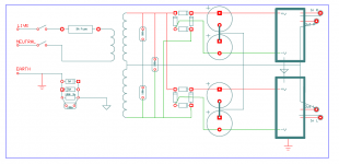
I have one suitable TX that has double output windings and would like to minimize crosstalk using double bridges and caps, forming two psu´s.
I am afraid this might cause hum due to using the same TX secondaries to feed both bridges in parallel.
Can it be done like this ?
Can I use only one TX to feed two prereg psu´s to power the Paradise ?
I have one suitable TX that has double output windings and would like to minimize crosstalk using double bridges and caps, forming two psu´s.
I am afraid this might cause hum due to using the same TX secondaries to feed both bridges in parallel.
Can it be done like this ?
Attachments
@Schwalbe,
soon a german version of building guide will be available.
That's fine, thank you for the information.
Cant see any problem with that, you should pay attention to the groundwiring though when you implement it.Hi
Can I use only one TX to feed two prereg psu´s to power the Paradise ?
I have one suitable TX that has double output windings and would like to minimize crosstalk using double bridges and caps, forming two psu´s.
I am afraid this might cause hum due to using the same TX secondaries to feed both bridges in parallel.
Can it be done like this ?
After all, you use the same powergrid anyway, for your mains
")
Hi
Can I use only one TX to feed two prereg psu´s to power the Paradise ?
I have one suitable TX that has double output windings and would like to minimize crosstalk using double bridges and caps, forming two psu´s.
I am afraid this might cause hum due to using the same TX secondaries to feed both bridges in parallel.
Can it be done like this ?
Yes you can, but you start off with a ground loop inherently build in and that may get to be a problem. I would advise to use 2 TX's to prevent this. If you select to use one TX then you need to take good care of the grounding scheme that you are going to use.
Yes you can, but you start off with a ground loop inherently build in and that may get to be a problem. I would advise to use 2 TX's to prevent this. If you select to use one TX then you need to take good care of the grounding scheme that you are going to use.
Hi Frans
That is my main concern... I once used a similar configuration and got a hum issue I could not solve.
Would you please point me the ground loop ?
What do you suggest as a good groundin scheme to avoid it´s intrusiveness ?
Hi Frans
That is my main concern... I once used a similar configuration and got a hum issue I could not solve.
Would you please point me the ground loop ?
What do you suggest as a good groundin scheme to avoid it´s intrusiveness ?
The 'ground loop' is more like a multiple connected ground system, where one connection is routed though the transformer (both amps share the same ground return to the TX) and the other connection is at the input (the shared return/ground of the cartridge/player). The shared cartridge connection can be broken by using a 5 wire connection to the player (connecting Left+ and Left- to the left amp, Right+ and Right- to the right amp, and having a separate player ground to the amp ground).
This is not something that I have experience with, and something that I would not advice. My advice is, get 2 TX's
Yes I know that.... I am actually using only one pre-regulator feeding the two boards and have been using that setup in other situations (my power amp for instance) but would like to profit from some better crosstalk isolation. The trouble is I am actualy working on a very tight budget and can not get another TX in the near future so I found this idea in the ESP pages.... Power Supply for Power Amplifiers
What bothers me more is that I can not identify the extra GND loop when going from one single prereg to two preregs in parallel using the same TX.
What bothers me more is that I can not identify the extra GND loop when going from one single prereg to two preregs in parallel using the same TX.
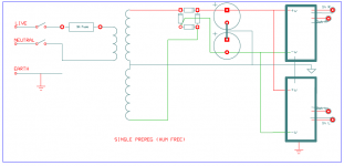
Just to make it clear I am using a single TX with single prereg without any hum.
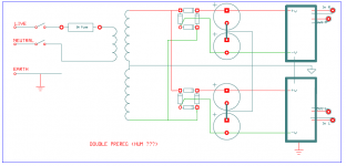
I removed some components so you can view easily what I mean.... the two pics below represent the single prereg that I am using now (perfect) and the new layout I would like to try.
Please let me know if you see an aditional GND Loop in the double prallel prereg sketch
I removed some components so you can view easily what I mean.... the two pics below represent the single prereg that I am using now (perfect) and the new layout I would like to try.
Please let me know if you see an aditional GND Loop in the double prallel prereg sketch
Attachments
Just to make it clear I am using a single TX with single prereg without any hum.
I removed some components so you can view easily what I mean.... the two pics below represent the single prereg that I am using now (perfect) and the new layout I would like to try.
Please let me know if you see an aditional GND Loop in the double prallel prereg sketch
If there is no hum in the first then I see no reason for hum in the second. Beyond that, check the player for the Q1, Q2 and Q3 connections.
Just one more question Frans, in your double mono schematic (two tx) I see you do not connect both grounds (left and right) together.
Also you do not make any reference to the output connections, so I admit we can leave both channels running completely independent without any common reference between them. What if there is a slight voltage difference between both channels grounds... does it procuce a current flowing in the output interconnects ? (I assume both output negatives will be joined inside the following preamp / power amp).
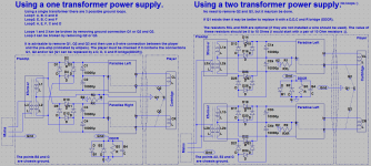
That’s right (spotted) and it is wrong (drawn). Check this out here is an updated (again) drawing
In this new arrangement for 2 TX's the circuit/signal-ground is only connected (left to right) in the attached amplifier, no loops possible any ware. Your concern about voltage differences is cared for by the RX, RXL and RXR resistors.Wow this is difficult to get right... but we will succeed
Attachments
Last edited:
Regarding TT connections, IMO Q2 and Q3 are not common because in good setups, the four wires comming out of the cart are always isolated from each other.
Connection Q1 to C is normal if C is the tonearm tubing, but C does never connect to any wire comming out of the cart.
That is why a single TX + prereg works.
But no harm in checking
I will leave the notes about it in the drawing.Now it looks cool.... wonderfull idea those 10 ohm resistors to take care of gnd voltage fluctuations... I am really glad you cared to hep me in this subject.
Now about chassis grounding and TT ground connection.... My best results where obtained by connecting the chassis directly to mains earth and connect the circuit gnd to the chassis via the DDCR.
So A2, E2 and G should be all connected together forming a star but isolated from the chassis. The TT arm GND wire should then be connected to this star gnd and not to the chassis.
Please take your time to review this because these are my findings... not a rule
Last edited: