MiiB,
you are making your own statements the "word of truth".
This is a dangerous attitude!
I am asking you again: Have you tried for yourself the solution I suggested you?
I am assuming, you haven't becuase if you did, you would have noticed how deeply better it sounds.
In turns you can do whatever you want, put a 200mF if you like, but if I comment something, it is because I have knowledge of what I am saying, I don't insult you to begin with BUT especially I have tried the solution I am suggesting against others and in the end I leave to the people to try that for their own and decide, you don't need to disergard everything I say in such a hursh manner.
Also, if I were you, I wouldn't be so quick to assume that subsonic filter on my system works better!
If you don't mind: who told you that? Have you listened to my system when I was gone?
I had 10mF on board and I didn't have any rumble/subsonic oscillation.
However using the value I suggested, slightly adjusted RIAA and soundstage opens up immensly and clarity with it.
Bass is just as deep as with a higher capacitor but more articulate and faster.
Sound of the phono is much less mellow made me fall asleep and wanted to turn it off.
It is not always a matter of numbers that define what sounds best for the most!
Your ultimate judge is your ear, therefore I couldn't reinforce this concept more and more: when design is nailed down, just stop simulating and make simple math calculations of cut off frequencies that don't even matter for the most and listen to the product and solution you want to consider as possible improvements (as long as they are reasonably supported by the general theory obviously).
I hope I cleared this out, and please let's just not debate on this and let's people decide for their own.
Also if you have some time, instead of making critics to suggestion I offer, please direct your brain energy to the MasterPiece's topic as this topic should be IMHO more brain-stimulating for an expert of your caliper.
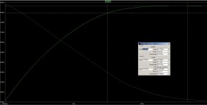
I attached the simulation for the circuit with the values suggested and -3dB curoff is about 3Hz, which should probably be more than enough.
Hope this helps.
you are making your own statements the "word of truth".
This is a dangerous attitude!
I am asking you again: Have you tried for yourself the solution I suggested you?
I am assuming, you haven't becuase if you did, you would have noticed how deeply better it sounds.
In turns you can do whatever you want, put a 200mF if you like, but if I comment something, it is because I have knowledge of what I am saying, I don't insult you to begin with BUT especially I have tried the solution I am suggesting against others and in the end I leave to the people to try that for their own and decide, you don't need to disergard everything I say in such a hursh manner.
Also, if I were you, I wouldn't be so quick to assume that subsonic filter on my system works better!
If you don't mind: who told you that? Have you listened to my system when I was gone?
I had 10mF on board and I didn't have any rumble/subsonic oscillation.
However using the value I suggested, slightly adjusted RIAA and soundstage opens up immensly and clarity with it.
Bass is just as deep as with a higher capacitor but more articulate and faster.
Sound of the phono is much less mellow made me fall asleep and wanted to turn it off.
It is not always a matter of numbers that define what sounds best for the most!
Your ultimate judge is your ear, therefore I couldn't reinforce this concept more and more: when design is nailed down, just stop simulating and make simple math calculations of cut off frequencies that don't even matter for the most and listen to the product and solution you want to consider as possible improvements (as long as they are reasonably supported by the general theory obviously).
I hope I cleared this out, and please let's just not debate on this and let's people decide for their own.
Also if you have some time, instead of making critics to suggestion I offer, please direct your brain energy to the MasterPiece's topic as this topic should be IMHO more brain-stimulating for an expert of your caliper.
I attached the simulation for the circuit with the values suggested and -3dB curoff is about 3Hz, which should probably be more than enough.
Hope this helps.
Attachments
With due respect passing that low with a TT source is looking for trouble AFAIK. Bloat is waiting around the corner for numerous reasons. That and the nature of masking in the human cochlea can conspire against an open sound. I believe that Stefanoo is on the right track in this IMHO.
Thanks Salas.
From the moment you can install less there is no issue. Each builder can try and tell in his own system. Problem would be if you needed more and you did not have PCB provision. Each one will not have same TT grade stability or speaker size anyway.
That is completely understandable and that is why I think this PCB was really, really smart to leave allocation for more ELCAPs and allocation for the RIAA section as well.
That is exactly what we did and we have discussed that the elcaps have an effect.
When you go back on the thread you will find my conversation with Ricardo about this.
He is also a freak of super linear RIIA and i have nothing against it.
MiiB and i decided on a slight elevated bass though as default values and that was also argued in detail. Period.
When you go back on the thread you will find my conversation with Ricardo about this.
He is also a freak of super linear RIIA and i have nothing against it.
MiiB and i decided on a slight elevated bass though as default values and that was also argued in detail. Period.
I did use lower EL cap values but did not reach a definitive math solution for the relation between it´s values and the 73.5k bass resistor... Maybe someone can give me a hint.
IMO modding EL cap values affects mostly the infrasonic response.
Modifying the bass resistor really affects the riaa curve in the audible range from 20 to 200hz with a peak between 30 and 50hz.
Anyway it is easy to experiment with and I found that we can adjust bass just by slightly mod the bass resistor.
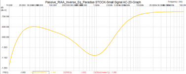
What I really find important is that with the stock values for the riaa:
9100 ohm and 33.3nF that should form the 318us time constant I get a slightly distorted riaa curve as in the pic below.
I do agree that using 9910 ohm and 32.09nF is a much better aproximation. (9910 x 0.03209 = 318)
IMO modding EL cap values affects mostly the infrasonic response.
Modifying the bass resistor really affects the riaa curve in the audible range from 20 to 200hz with a peak between 30 and 50hz.
Anyway it is easy to experiment with and I found that we can adjust bass just by slightly mod the bass resistor.
What I really find important is that with the stock values for the riaa:
9100 ohm and 33.3nF that should form the 318us time constant I get a slightly distorted riaa curve as in the pic below.
I do agree that using 9910 ohm and 32.09nF is a much better aproximation. (9910 x 0.03209 = 318)
Attachments
Last edited:
I did use lower EL cap values but did not reach a definitive math solution for the relation between it´s values and the 73.5k bass resistor... Maybe someone can give me a hint.
Sorry can not as with my better to 1 dB current test rig. (Think that it has been if not proven maybe just make one think two times before dismissing it)
I can not get pictures downloads camera wuld not work and all jou will get is wax....
One got to do same work and try on its own sistem and set things up for its own taste.
We are talking tiny litle bit of tweaks here and there just to get that tiny litle bit better and that is strictly dependent on what one consider better
All one shuld espect from this is hints on how to satisfy one own personal taste.
For now and I care only for those that are waiting for the bits and pieces be reasured that Paradise work first time so circuit is sound it sound prety good so designer know much more than I do (Consider my baad aplication of english humor and maybe one get it) boards are sturdy enoug to take a lot of abuse and design let you play with things, It is to early to try to impose precing on the general population so I am over and out and this is getting a bit......
Last edited:
Cartridge Question
Hi,
I currently have the choice of two Phono-Preamp Projects waiting to be soldered over Winter. I would like to base my choice with which to start on the fact which one handles my current favorite Cartridge better.
It's a a "Low-Z" MM Cartridge with 100R recommended loading, 3R DC Resistance, 1mH Inductivity and ultra-low (0,06mv Edit1cm/s) output. The output in fact is so low, that the Trigon Advance in full MC Amplification will not handle it properly.
Will the Paradise be able to work well with such a rare beast?
Any hints welcome
Mike
Hi,
I currently have the choice of two Phono-Preamp Projects waiting to be soldered over Winter. I would like to base my choice with which to start on the fact which one handles my current favorite Cartridge better.
It's a a "Low-Z" MM Cartridge with 100R recommended loading, 3R DC Resistance, 1mH Inductivity and ultra-low (0,06mv Edit
1cm/s) output. The output in fact is so low, that the Trigon Advance in full MC Amplification will not handle it properly.Will the Paradise be able to work well with such a rare beast?
Any hints welcome
Mike
Last edited:
The gain can be brought up theoretical in 3 ways :
1 : Lower the emitter resistors, if you half the value for example
2 : Raise the values of the resistors in the RIAA to double for example and lower the value
of the caps in half.
Both methods have the disadvantage that the distortion goes up in proportion to the change. It still may be good enough to not create an audible problem. It has to be checked if this changes have an effect on the DC conditions, servo etc.
3 : Use an input transformer, i think this is the best option. 0,06mV is simply extremely low for an active phono.
You shouldn't beWell as there aren't that much low Output MMs I'm surprised Holger didn't realise. It's a Pickering XLZ-7500S.
.I am not that deep into vintage cartridges.
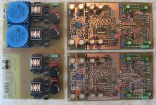
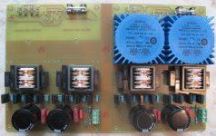
This is my PCB almost all assembled. The Pre-Reg is working fine, just waiting for the last part order to get the remaining transformers. The preamp PCB are only missing the 337/327 matched transistors. I'll make the RC filter small PCB today while continuing to measure the transistors HFE.