The Leds are 3mm 2mA. You can order Osram, Knightbridge, whatever. I use Reichelt because they usually are in the lower price range. You can even order surplus from Pollin.
I use 1uF MKT from WIMA; also Reichelt. You have to watch the footprint. In the PSU there is an option, in the Phono part, not. 7.5mm is fine. EPCOS, RIFA, are other options. They perform more or less the same. If you want P-P use WIMA MKP4, they are the smallest.
Most green Leds with 2mA nominal have a forward drop of around 1,8V.
Near all green led's will do, if they handle at the least 1mA current. Near all green led's will have a forward drop of (about) 1.7 volts (and that will do).
Near all green leds
Oh Well, 10mm ones then.
(shame that a 20mm does close to 6V at 2mA)
Thank you Frans and Jacco
This is what I needed to know " if they handle at the least 1mA current."
How far can we go from the 1.7 Vdrop margin ?
I am using yellow leds.. did not measure them but these could have higher Vdrop (1.8 to 1.9)
As far as you dare
") and if the output voltage gets to high, you can just use one less (and bridge the open spot in the chain of led's).
and if the output voltage gets to high, you can just use one less (and bridge the open spot in the chain of led's).Oh Well, 10mm ones then.
(shame that a 20mm does close to 6V at 2mA)
I would presume that the 20mm one holds actualy 3 leds (don't you think, but I have been wrong before
).I would presume that the 20mm one holds actualy 3 leds
Three 20mm LEDs on each side may look pretty too.
(are you implying that I am able to think ?)
I would also like to experiment several types of caps in the output of the shunts... there is a 10uF... can I use very low ESR types ? .... Will it withstand a film cap without oscilating ?
It is not advised to use low (and very low) esr types on the output of the shunt, other shunt designers say that it may even be better to leave the capacitor out. My opinion is that the best practice is to install a 'normal' 'high
' esr type it's purpose is mostly to suppress (lower the output impedance of the psu) at high frequencies (> 1 Mhz). One replacement I would like to see tested is, a 2 Ohm resistor in series with a high quality 5..10 uF capacitor.On the other hand, no one has been able to make this thing oscillate so try it
and I already did some weird thing to it (including using more than 2 M of intertwined wire between the PSU and the attached electronics).I used a 10uF 35V Panasonic FM without problem. I measured the ESR to be around 1 Ohm with this cap.
Told you so
On the other hand, no one has been able to make this thing oscillate so try it and I already did some weird thing to it (including using more than 2 Mtr of intertwined wire between the PSU and the attached electronics).
The point is (and that is why others may advice against capacitor(s) on the output of the shunt) that the capacitor lowers the open loop gain of the shunt and thus may (in fact) up the output impedance. My simulations, with capacitor esr at about 1 ohm, show little of this effect.
Perfect... I believe a 10u (or less) film in series with 1ohm will work then.It is not advised to use low (and very low) esr types on the output of the shunt, other shunt designers say that it may even be better to leave the capacitor out. My opinion is that the best practice is to install a 'normal' 'high
On the other hand, no one has been able to make this thing oscillate so try it
This cap (as well as the one filtering Vref) tend to leave it's signature so a good film cap might do wonders in the output
Yesterday evening I have experimented a little bit with a couple of circuits trying to determine DC performance and Noise performance.
While noisewise, they are pretty close to each other, the DC performance of the simple source follower is way better than the big borther (complementary's).
I kind of grasp why the DC performance of the source follower would be better compared to the complementary version.
Nevertheless, my concern is:
Is the Fet version of the Paradise (see picture below) going to have the same DC issue of the complementary version?
What makes the Paradise behave so well DC-wise?
DC performance are really important when the stage is followed by another high gain stage to top off the necessary gain.
What do you guys think?
Attachments
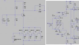
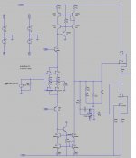
there's no DC issues with the Fet version, but you cant get enough gain using the servo the way you do.. reason is that you want the servo to have some authority so the output resistor can't be too big, this resistor is in paralleled to the RIAA shunt. which in return affects the RIAA network. max gain with this servo is app 52 dB, you really want app 62-63 dB
In your Fet version you have trouble controlling the current drive and thus the offset, better would be to use the paradise servo-ed housekeeping
In your Fet version you have trouble controlling the current drive and thus the offset, better would be to use the paradise servo-ed housekeeping
there's no DC issues with the Fet version, but you cant get enough gain using the servo the way you do.. reason is that you want the servo to have some authority so the output resistor can't be too big, this resistor is in paralleled to the RIAA shunt. which in return affects the RIAA network. max gain with this servo is app 52 dB, you really want app 62-63 dB
In your Fet version you have trouble controlling the current drive and thus the offset, better would be to use the paradise servo-ed housekeeping
Let me think about what you said and make some more simulations and I will get back to you.
wow.....it must have been exciting to be able to see the original pictures in back and white!!
Too bad she killed herself!
You may have not realized this, I did not
, but this was the first post on page 666. http://en.wikipedia.org/wiki/666_(number) see 2.1. For as far as I can see, we escaped further disaster and left the page a bit later No lights yet, here a small status (stupidity) report,
Last saterday the board was compleated, sunday during the day it was mounted, and sunday evening I destroyed it
After first power up I could not set idle current, so I took the meter and the nearest probing pin (it was a (to) large one), and started metering some points. The next thing is, I shorted 70 Volts against the Vas-cascode, this destroyed the cascode and put lots of volts on the opamps... you can guess it from there.
Next weekend there will be time, and the fight goes on ... will be continued ...
One small update, the power supply has been fixed. And the LME49710's have been checked. To my amazement thy survived (running on +15 and -25 volts). So the big disasters is in fact not so big at all
Next I have to replace the vas-transistors and figure why I could not set bias (I di suspect one of the driver mosfets). I'l b' b'ck
