(2.5/0.002) Vpp in your asc?
yes, you are correct.
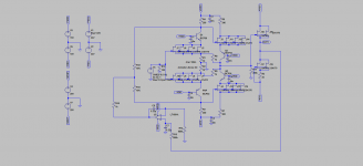
Stefano, here is a circuit that is similar to the JC Vendetta. Here the servo is connected to the source resistors of the input stage. You are not using a folded cascode so you have to use a non inverting servo in your case. The other option would be to make the second stage cascades floating and connect the servo there.
Attachments
Joachim,
I am still working on simulation for servo gain stage and buffer.
Does the servo look good?
In this case it is not on the signal path, but I am not sure it could work in practive.
It simulates just fine and with an input offset it acts and zeros the output out.
Would you mind comment it?
Thanks,
I am still working on simulation for servo gain stage and buffer.
Does the servo look good?
In this case it is not on the signal path, but I am not sure it could work in practive.
It simulates just fine and with an input offset it acts and zeros the output out.
Would you mind comment it?
Thanks,
Attachments
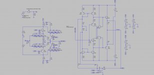
Instead of the two resistors setting the current you could opt for a current source, this is a replicate of the household I did for the paradise... Now the servo works by injecting current into circuit to make the two halves amplify the same... This is for me an optimal way of implementing a servo, here it work just like an automated trimmer. Will it still work if you make R14/R30 larger....like 47 Kohms...??
I have tried to servo buffers...but somehow it's difficult, with one exception the single ended N-Jfet buffer, To me that is a beautiful design..
I have tried to servo buffers...but somehow it's difficult, with one exception the single ended N-Jfet buffer, To me that is a beautiful design..
Last edited:
Joachim,
I am still working on simulation for servo gain stage and buffer.
Does the servo look good?
In this case it is not on the signal path, but I am not sure it could work in practive.
It simulates just fine and with an input offset it acts and zeros the output out.
Would you mind comment it?
Thanks,
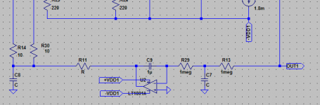
I would make R14/30 of a higher value, also I would split the input of the servo into 2 500K's and one 1uF to ground (adding a lp-filter in front of the servo). Also I would add an lp-filter on the output of the servo, this will eliminate any noise that may come from the servo.
Attachments
Last edited:
You run the servo into a very low impedance. I hope that does not bring trouble. in your gain stage i do not 100% understand the biasing of the second stage. Why R16, R16 ?
That is a simple way that I find it very easy to implement, to degenerate the second stage and at the same time set the current bias it, which will simply be the voltage drop on the first stage resistor minus the conduction voltage of the fet divided by the second stage's resistor.
In one of previous prototypes I was running the gainstage wihtout the current feedback but only with a local feedback on the second stage from output to the gate of the fet.
That worked fine except from a power dissipation standpoint, which pushes me now to try the gainstage with a current feedback as shown in the circuit here.
Nevertheles the way I will bring the feedback will have to be determined whether will be current global feedbak or local degeneration based on listening tests. Either way I have to solve the issue with the servo which seems to be pretty significant since I am not very skilled and especially when it comes to servos.
Last edited:
yes, this is correct.
Nevertheless, in this case by having an higher gm I can decrease the degeneration of first and second stage, thus increasing current and then lower the feedback current up to the limit of current capaciblity for the ouptu stage (in this case the second stage who carries the current for the feedback).
Although this is a good method to lower noise and output impedence, it is probably not ideal from a sonical standpoint and that probably circles back to your main observation.