This is what I came up with (I do not want to start a new thread on this, but still I want to show the 'thing', so here it is), I guess I am spending to much time at the ATL
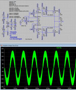
What about this, I can do 70 Watt class A in 4 Ohm (or 150 Watt class A in 8 Ohm bridged). The amplifier has 14 components (and that includes the loudspeaker). The simulation FFT shows first harmonic at -100 dB or better (that is at clipping and at 10 Khz). There is no global feedback. There are no capacitors in the circuit.
So that is what I get when I cannot sleep. Maybe now I get some sleep ...")
One thing more about the circuit, the amplifier delivers power by:
Pout = I * I * R (normal amps do (V * V) / R ).
This will give a different listening experience (due to the fact that (for a normal loudspeaker (system)) R is not constant over the frequency range) than with a ‘conventional’ amplifier.
Frans, do you like to build it or is this just a circuit idea ?
I’m thinking about it, but at the moment I am building the other amp that I showed the board for (the board is ready and ordered (10 pcs)), and at work it is make or break (my work planning until September looks like 70 or more hours/week), so it is difficult (to say the least).
On the other hand, yes I would love to build it. I’m intrigued by it, I have never ever seen something like it (most current delivering design do float the loudspeaker to measure current, and thus cannot be bridged).
The figures are also very intriguing, as noted by other people, the complexity lies in the power supply, and I can do that (power supplies
). Maybe a smaller 100 Watt bridged version (running of 30 Volts +/-) would be nice.Anyway, not at this moment, but for sure at the end of the summer, I think it should be build. If someone else is willing to give it a go, then we should start a new thread and I will support it (at this moment).
Yes, we should do a thread about power amps. My research into Phono- and Preamps is more or less done and i got interested in power amps. That is not my forte but i managed to build a good sounding Simple Symmetric and i am contribution on Lazy Cats thread.
Does the amp from Post 6020 need a constant impedance over frequency from the speaker ? If not, then this is really new or at least i have not seen it.
Does the amp from Post 6020 need a constant impedance over frequency from the speaker ? If not, then this is really new or at least i have not seen it.
I talked about the Thats balanced line drivers and receivers.
I use them with very good results. Here is a paper about the technology :http://www.jensen-transformers.com/an/ingenaes.pdf
If one listen to recorded stuff chances are that sound came from those if not from 5532
Pitty about ofset of That stuff (who beter than you to get around it?)
That all signals have passed through an NE5534 or similar is not universally true.
Neve was involved in developing the NE5534 but the way he used them in the famous boards from the 70th and 80th was not simple using that Opamp but as far as i know he biased them into class A and skipped the output stage. Older boards had tubes and modern boards sometime have discrete building blocks. Of cause there are many audiophile recording that go straight into the recorder or are cut direct to disc.
I did not have offset problems with the Thats chip i use. I use the 1200 series as Balanced to Unbalanced converter in the commercial Suesskind Rauschfrei without that problem.
Yes, we should do a thread about power amps.
I would like that. I will be there, and when I have build the first 'final' of the current amplifier that I am building then I will publish it there.
My research into Phono- and Preamps is more or less done and i got interested in power amps. That is not my forte but i managed to build a good sounding Simple Symmetric and i am contribution on Lazy Cats thread.
I did see you there (I'm lurking only) (once I did show my version of a SSA). http://www.diyaudio.com/forums/solid-state/193923-simple-symetrical-amplifier-53.html#post2735781
Does the amp from Post 6020 need a constant impedance over frequency from the speaker ? If not, then this is really new or at least i have not seen it.
To deliver constant power to an actual loudspeaker it would, but this is also true for any other amplifier. But this one delivers power as I * I * R and that makes it different. Most (if not all) loudspeaker systems are tuned for (V * V) / R amplifiers (most of them). Due to this difference, there will be a difference of sound between amplifiers of their types when connected to loudspeaker systems that do not have constant impedance (for better or worse).
Maybe an amplifier like this should drive a transformer coupled loudspeaker
Last edited:
Joachim,
What do I read; you are up for a review...
Good luck with that
Regards,
Frans.
Help - Rational Quality Manager help
Looking forward to your review...
What do I read; you are up for a review...
Good luck with that
Regards,
Frans.
Help - Rational Quality Manager help

This is what I came up with (I do not want to start a new thread on this, but still I want to show the 'thing', so here it is), I guess I am spending to much time at the ATL
What about this, I can do 70 Watt class A in 4 Ohm (or 150 Watt class A in 8 Ohm bridged). The amplifier has 14 components (and that includes the loudspeaker). The simulation FFT shows first harmonic at -100 dB or better (that is at clipping and at 10 Khz). There is no global feedback. There are no capacitors in the circuit.
So that is what I get when I cannot sleep. Maybe now I get some sleep ...
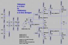
This one is way better, it needs a simple (unregulated) main power supply, the schema in the previous post needed a highly regulated PSU and the PSU used for {ivas} needed to be strongly referenced to the main PSU and also 'exactly' 15V higher (lower for the negative side).
This is all gone now, the {ivas} current is referenced against the main PSU. As the reference voltages for {ivas} and {iout} are the same, no need for strong PSU regulation, and easy switch on/off (as long as the opamp PSU are faster than the main PSU).
Now I think a test sample can be built by using battery PSU's for the opamps and a simple transformer/rectifier/capacitor PSU for the main PSU.
Attachments
Last week I found this site, have a look (I liked it) Welcome - Fritzing
This one is way better, it needs a simple (unregulated) main power supply, the schema in the previous post needed a highly regulated PSU and the PSU used for {ivas} needed to be strongly referenced to the main PSU and also 'exactly' 15V higher (lower for the negative side).
This is all gone now, the {ivas} current is referenced against the main PSU. As the reference voltages for {ivas} and {iout} are the same, no need for strong PSU regulation, and easy switch on/off (as long as the opamp PSU are faster than the main PSU).
Now I think a test sample can be built by using battery PSU's for the opamps and a simple transformer/rectifier/capacitor PSU for the main PSU.
The next step is class B, the attached image shows a class B version of the ‘no global feedback’-amp. The main problem is: it oscillates
. I do not worry too much about that because no one wants a class B amp. This class B version must now be updated to class AB, that must be done by introducing a bias current and at the moment I cannot see how. Any Ideas?