Update: The numbers above for power consumption are the minimal's the maximum's are (when the RIAA is disconnected) 34 * 320 = 10.88 Watt or 40 * 320 = 12.8 Watt.
Regards,
Frans.
Good input - the new Paradise has jumper positions on the PCB so the regulators can be tested and adjusted before hooking up the amplifier section. Definitely something to be done on the bench, not in the closed case, and not to leave it idling for hours since the heatsink will be pretty hot then....
Sorry to see this a little late. The PSU runs at 160 mA, so you need 2 x 160 mA = 320 mA minimal. You need 34 Volts on the regulator input (or a bit more, up to 40 Volts will be o.k.). The power disipation will be 34 - 24 * 320 = 3.2 Watt minimal ans 40 - 24 * 320 = 5.2 Watt maximall. More information can be found in message 5650 http://www.diyaudio.com/forums/analogue-source/154210-mpp-283.html#post2970304.
Regards,
Frans.
Thank you Frans.
That leaves enough headroom to use a 30V TX. In fact I will use two 80VA 30V TX to build a double mono setup.
Is 40Vin the absolute max value ? Can I input 42V ?
Thank you Frans.
That leaves enough headroom to use a 30V TX. In fact I will use two 80VA 30V TX to build a double mono setup.
Is 40Vin the absolute max value ? Can I input 42V ?
It will handle 42Volts, in a way I like that number; I may even prefer it
") The components selected will handle even more than that, but the heat sink will not be sufficient if you pass 15Watts per channel.
The components selected will handle even more than that, but the heat sink will not be sufficient if you pass 15Watts per channel.See also: The Hitchhiker's Guide to the Galaxy - Wikipedia, the free encyclopedia
Hesener you have paypall...
Going to start matching 1000 each
BC32740BU and BC33740BU
with this
http://www.diyaudio.com/forums/solid-state/151253-diy-curve-tracer-pc.html
all from Fairchild direct same production bacth
Shull be prety tight
If any of you need same just PM.
Going to start matching 1000 each
BC32740BU and BC33740BU
with this
http://www.diyaudio.com/forums/solid-state/151253-diy-curve-tracer-pc.html
all from Fairchild direct same production bacth
Shull be prety tight
If any of you need same just PM.
many thanks
hadn't seen this curve tracer, really cool!!
Hi Joachim
I am going to get started tomorow and let see
hesener
My tanks to you
Curve tracer works just as written on tin (best money I ever spent, on equipment, was my comment.
... and not the only one to have one here...
(maybe beter not infringe on other privacy whitout nod)
Be nice to set up same parameters and match stuff consistentley world vide
And altrought perfectley functional it could benefit whit a software update to make sorting easier which is way out of my capabilities.
Hint
Me gready boyz
many thanks
hadn't seen this curve tracer, really cool!!
I have one
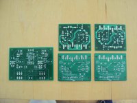
I got PCBs from Marcin.
The High Speed Preamp in the metal can version and 4 Power Buffers because i would like to try balanced.
I think they came out nice with ground plane on one side.
Looks very good, now I want to hear all this...
Looks very good, now I want to hear all this...
Me too. I am almost done with stuffing the preamp - I just suck with my parts housekeeping so while I was sure I have all capacitors....now I need to order them and wait another 48hrs.
:/
First bunch of BC337 40BU
Gone trough curve tracer
50 down 950 to go
It takes about 15 minutes to run the test
Sorting the curves much longer as those have no label so is hi light each one in turn.
So far reading HFE at 0.6V I have 1 at 430 is and one at 608
The big bunch is all around 510 and 550
I take that marching should be at lest be done for the transistors on same part of the circuit
For example matched quads for current mirrors.
How close should the marching be?
For example the 2nd and 3rd curves from top look good enough for matched pair?
Attachments
Last edited:
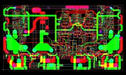
Done, I't's an Amp I Think
All,
This one is done, the design program has no complaints all connections are accounted for and it is ready for the press. This being my first major Amplifier design, are there any people here with some pointers, hints and 'plain old' good advice
All,
This one is done, the design program has no complaints all connections are accounted for and it is ready for the press. This being my first major Amplifier design, are there any people here with some pointers, hints and 'plain old' good advice