Congratulations to you every one of you!
I am willing to order 1000 each here (BC327-40-BK and BC337-40-BK) @ 0.015 cents
Transistors DIOTEC. 14 products in stock
Any one that will take 500 each from me?
I want to have 500 pcs too.
Please send me a PM whre i should send the money.
Regards
Sam
Hey, i absolutley have to join a forthcoming PCB-buy. count me in for 100-200 Q's if possible.
Adjusting R33 and R35 is not tweaking, just set it for the desired voltage for optimum cascode bias.
In practice, I tried with a trim pot, and then solderd a coincidential fixed resistor in.
Rüdiger
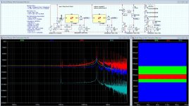
EDIT: Michael, I can't read it: What are the parameters of the input Voltage Source (you use for the distortion measurement)
Adjusting R33 and R35 is not tweaking, just set it for the desired voltage for optimum cascode bias.
In practice, I tried with a trim pot, and then solderd a coincidential fixed resistor in.
Rüdiger
EDIT: Michael, I can't read it: What are the parameters of the input Voltage Source (you use for the distortion measurement)
Last edited:
I want to have 500 pcs too.
Please send me a PM whre i should send the money.
Regards
Sam
PM me and as soon as I receive the goods I will notify you, and other people that PM'ed me. The order has been placed and payed.
Regards,
Frans.
Have you already simulated that whole schebang ?
I think Frans is our PSU man and he has drawn up something before.
Please Frans, jump in if you like when your read this.
Still working on the final version (there is a (small) one wire change). I will publish in the next hour.
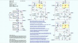
About the servo, normally I would use a somewhat bigger capacitor (1u poly) and smaller resistors 1Meg or even 100K. My opamp of choice for servos is the OPA134 (like D.Self
") )
)Sorry Joachim one small change to make, the capacitor that was placed between the transistor base and ground has been moved to (between) transistor base and output. This gives a much improved load response.
Attached are may (currently final) research and power supply schemas with annotations. Also attached are the LTspice source files. Next thing for me (is build the real thing).
There are a positive and a negative supply and one variation that uses (almost) the same components for the negative supply as for the positive.
Also note that BC327 and BC337 transistors can be used to replace the BC550 and BC560.
And finaly, if you want more than 100 mA you should replace the single transistor (in the gyrator) with a Sziklai pair having a Rcb of about 100 Ohm. (more usage for your BC327 and BC337 transistors).