quick question...
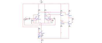
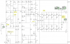
Hi Joachim, maybe I am "schief gewickelt" but I have a quick question, as per attached picture of the input stage of the starless phono stage. I am planning to build transimpedance (no problem there), but then I thought to put jumpers and try transconductance as well.
I believe that ground connection (circled red) should not be there - if it were, the lower half of the circuit would not contribute anything, is my thinking correct? I thought I ask before a few hours debugging.....
thanks in advance
Attachments
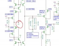
That question came up earlier in this thread. The ground connection looks strange but the circuit works nevertheless. There was also a simulation done by our friend in Litunia and i think he also build it and made it work. Somehow this floating double cascode, symmetric mirror is strange anyway. It did not simply fly out of my head but was a reaction to the question what can be done to fight the P-Channel problem. It was also inspired by the CEN-SEN thread. There i contributed a DC coupled version that also used current mirrors.
So the Starless would not exist without this forum.
So the Starless would not exist without this forum.
OK thanks. Thinking about it, without the ground connection the input JFET would act as a source follower against the (high) drain impedance of the lower cascade, current possibly would not change and so there would be no output signal, I guess. But with the ground connection, the upper half works as an amplifier, and the lower half as a current source into the output node without much contribution. I would expect the transimpedance version to have higher gain, as both halves will contribute (if it actually can be compared.... what is the input voltage at 0 input impedance?)
will try both. Today I should be able to fix it all..... thanks for the help, much appreciated!
will try both. Today I should be able to fix it all..... thanks for the help, much appreciated!
Yes, that´s the way i see it too, Gm stage loaded by a constant current source plus RIAA.
Curiously in praxis the transconductance version can sound louder. That is when you use
a cartridge with rather high impedance like the DL103. It´s 40 Ohms give less gain with the transimpedance version because the 40 Ohm react like degeneration. You get less distortion but also less gain. That was a problem our Litunia contributor had in the beginning. I then added the helper transistors ( raises the output impedance of the mirror times 2 for 6dB more gain ) and we raised the values a bit in the RIAA, so he got around 60dB of gain in the end. The transconductance circuit´s gain is independent of the cartridge impedance because the gate of the Fet isolates the cartridge from the amplification chain.
Hi hesener,
Correct, but the lower part actually contributes half the sqrt root of total noise. It could be made quieter.But with the ground connection, the upper half works as an amplifier, and the lower half as a current source into the output node without much contribution.
Well no, in both arrangements lower cascode and mirror is acting only as ccs. We discussed gain issues and differences with Joachim quite thoroughly I guess. I built it "as is" only because I could drop in p/n fet input pair for comparison without any major changes, plus servoing "lazy" lower current mirror gives good results so dc coupling is possible but I'm still experimenting on this. Actually for usual transconductance input, circuit can be rearranged to SE. It has lower noise, same open loop bandwith, gain and thd distribution. Coupling cap comes as penalty. I already build 1 channel, and that zener referenced ccs has very good tempco stability. If going for ultimate noise characteristics, 4x2sk170 can be paralleled, but J310 wont cut it for cascoding, PN4391 would do ok.I would expect the transimpedance version to have higher gain, as both halves will contribute.
Attachments
If you run the buffer on +- supply you can place the cap inside, then you can use a much smaller and better one...like the Rel tin polystyrene.
Yes MiiB, all the usual tricks are valid if using bipolar supply. Even zener ccs could be servoed for dc coupling. I'm still working on this, it's just lack of spare time that is slowing me down these days.
On thing I like with the single ended...is the way the current is set through the input via the current source in the second leg...with this circuit the BF862 would be at very very good part, since they can operate at lover currents and still be quiet, but at the expense of DC coupling...
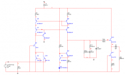
Sampler, mighty fine SE circuit you made !
There is only the bleeder resistor missing over Q9.
Several J310 can be paralleled for more juice.
Hi Joachim,
Thank you for kind word. Yep sorry for this one, some 3k i guess, I drawn it from memory while still at work (noughty me
 ). RIAA shunt resistor could be off too then.. well it's always like that when something is done in a hurry.
 I'm also cooking something that could be all n channel, balanced, dc coupled input stage, it's just have to crystallize a bit as a concept before I post something. But I will surely do sooner or later
P.S. Your folded cascode input stage didn't slipped unnoticed, nice concept, some resemblance to vendeta I guess, just servoing current sources and bjt's instead fets for cascode. Who knows, could be even better !
Yes, 2 kOhm to 3 KOhm is fine.
I am very interested in your new input stage of cause.
Do you refer to the driven cascode where the bipolar folded BJT is driven by the source resistor too ? That could even be combined with a bootstrap ( Hawsford ) cascode so the BJT is driven from all 3 legs. Did not have enough time to work that out.
The Vedetta is different but the folded cacode is also driven from the gate and the source.
Yes, 2 kOhm to 3 KOhm is fine.
I am very interested in your new input stage of cause.
Do you refer to the driven cascode where the bipolar folded BJT is driven by the source resistor too ? That could even be combined with a bootstrap ( Hawsford ) cascode so the BJT is driven from all 3 legs. Did not have enough time to work that out.
The Vedetta is different but the folded cacode is also driven from the gate and the source.
Yes, driven folded cascode. Anyhow, I think it deserves be taken little further when time allows of course. Here is the original SE from home pc. Circuit should be not far from reality, I measured only 0.3db variation from RIAA curve in proto with values shown.
MiiB,
I have 50 BF682 waiting for sorting. It's such a pita dealing with sot23, that I tend to always put this task aside... But you are right, it's ideal for this application.
Attachments
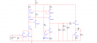

The circuit could be setup parallel symmetric. Anyway, i found the driven cascode part on a current source interesting. Driven cascodes show up the last 4 weeks everywhere. Maybe some people found inspiration here ...
Anyway, it is and old concept going back to Tectronik in the 70th as far as i know.
Anyway, it is and old concept going back to Tectronik in the 70th as far as i know.
I've measured around 63dB. That is with 7.4ma Ids and -0.44v Vp 2sk's, so beta was ~35.Sampler
how much is the gain at 1KHz..??
Of course, but I would select pair with at least 4V Vp, that would lead to about 1.4V on 2sk drains. Just to be on the safe side.Several J310 can be paralleled for more juice.
Ouch... when I see something like that with zilion caps just to make it stable in sim, I already see my self sitting through the night and looking which pcb track has extra uH and makes thing oscillate wildlythis is a circuit by magic box.
I wouldn't be surprised, as it was golden era of analog wizardry. Thats why it's always great fun for me to repair older tek's, history unfolding before your eyes. Here is another good one.Anyway, it is and old concept going back to Tectronik in the 70th as far as i know.
Funny thing.
I was tinkering with "my" input stage and started reading JC-3 thread, and.... well seems I've kind a was reinventing the wheel
My sim screen cap is attached. Hmm... back to the drawing board...