I am very tempted to do it but need some more info so I can fine tune it in the end.
How is the 2187uS determined in your schematic ?
As you do not use a Riaa input resistor, I guess this value should be determined by 1st stage output impedance // R15 = 412k x C7. In this case C7 should be 5.3nF.
To determine the 750uS pole 412k x C8 so C8 would need to be 1.8nF.
To determine the 318uS pole using C7 = 5.3nF we would need R16 to be 59.9kohm.
Does it make sence to you or am I missing something.... Why did you not include an input resistor in the Riaa circuit ?
I am very tempted to do it but need some more info so I can fine tune it in the end.
How is the 2187uS determined in your schematic ?
As you do not use a Riaa input resistor, I guess this value should be determined by 1st stage output impedance // R15 = 412k x C7. In this case C7 should be 5.3nF.
To determine the 750uS pole 412k x C8 so C8 would need to be 1.8nF.
To determine the 318uS pole using C7 = 5.3nF we would need R16 to be 59.9kohm.
Does it make sence to you or am I missing something.... Why did you not include an input resistor in the Riaa circuit ?
It's current output so riaa is formed by changeing signal levels to ground, think the output mirrors ensure a rather highish output impedance, I have simulated this circuit and treated output impedance as beeing ideal, this gives a riaa curve with less than 0,25 dB difference.....From the theoretical. Calculated with LaPlace tranformation and timeconstants.
Ok... in that case, the usual methods to calc Riaa values do not aply .... How do you do it ?
Hi RCruz,
Floating input transconductance circuit does not work, I checked it in my circuit as simulators are somehow flaky about floating things. But I think I was wrong about grounded sources, it should work, at least it sim'med ok.
Output impedance of current sources are frequency and power supply dependable, so when calculating by hand the math is quite strong with this one.
Why you don't want to try transimpedance arrangement ? The only down side is that you have to be extra careful with input offset and don't fool around with live circuit when cart is connected, or you could fry it (as MiiB has pointed).
Anyhow, how much gain do you need ? I think I can sim something for you.
Ok... in that case, the usual methods to calc Riaa values do not aply .... How do you do it ?
See post 2962.
"If you want to use 10n for C7 I arrive at R15 218k7, R16 31k8 and C8 3n43. "
These can be scaled accordingly for different gain.
The values apply for infinite output impedance at that point.
If the impedance is lower only R15 has to be adjusted.
Formulas may follow tomorrow if you need them.
Here are the theoretical values for a transimpedance RIAA. This values assume an infinite output impedance of the current source ( mirror ) and an infinite input impedance of the buffer. It is true. Only R1 has to be adjusted.
Attachments
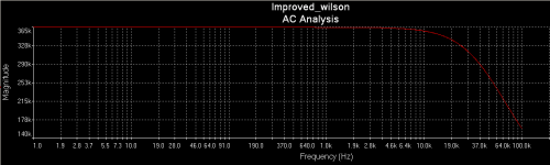
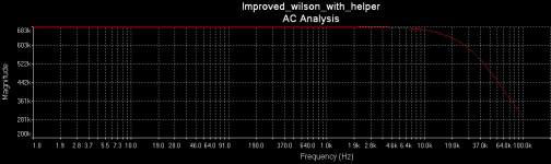
Yes Joachim, you were right, it works just fine. Here is output impedance plots of current mirrors with -+18V supply and 374 Ohm emitter resistors. I think it's really worth using helper transistors, as with higher output impedance you get better frequency response, for the same theoretical riaa values. So adding 500k to the ground already gives you almost straight impedance line to the 25k Hz and perfect riaa compliance.
Attachments
")
Well, i do not want to disturb the proceedings but a second helper instead of the short on the top mirror could even be better.
Would you explain that please ?
What schematic are you talking about ?
Where does the second helper fit ?
I hope so. I will be in Vienna the next weekend. Yes, we badly need better speakers.
Here is it, Ricardo. The input can be setup in two ways. Transconductance and alternative Transimpedance. The Transconductance circuit has gain independent from the cartridge impedance, but we loose the advantage of less distortion with less gain when the cartridge impedance goes up. A good compromise can be found by juggling the RIAA components. It should not have more gain then necessary for best overload margin and least amount of distortion. Transimpedance RIAA needs different thinking then normal passive or active RIAA.
Here is it, Ricardo. The input can be setup in two ways. Transconductance and alternative Transimpedance. The Transconductance circuit has gain independent from the cartridge impedance, but we loose the advantage of less distortion with less gain when the cartridge impedance goes up. A good compromise can be found by juggling the RIAA components. It should not have more gain then necessary for best overload margin and least amount of distortion. Transimpedance RIAA needs different thinking then normal passive or active RIAA.
Attachments
High-end faces a serious problem simply because we get better sound from a set of good headphones on an Ipod.
Never has so many young people been listening to two channel music, but they just don't drift into high-end, simply because what we create is not good enough...and it's the speakers that is that poses the biggest problem for the missing performance, the drive units are simply not good enough....We have still to better the Old CLS-1 in terms of magic and being there....!!
I believe the C-1.1 (what else to call a successer to the C-1.0) will leave a great imprint on those who listen, it has a lot of the magic and sense of intimacy with the performers emotions...of the OLD CLS-1.. I am very pleased.
Last edited: