Will do absolutley If I can give back just this litle bit to the Likes of you and Papa
I am more than happy.
Sound shuld be better than LAC less Jhonson noise even less than Lithium (I dont like Lithium cells as they have a tendency to explode)
NIC got more Mr Jhonson than LAC
I think I am covered now with those others that may want to use the Idea and hit the patent office (and we know a few..)
I was looking at Down the Rabbit hole article and that is one baby I would like to try.
How long would charge last with 2 of those is the problem and my question?
Last edited:


I was planning on the Pilgrim kit in the next 3 months or so
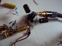
I have at present a split ria passive(easier to design for me) stage with LT1028 INA see 2 pictures
and was thinking about changing the imput and use a similar stage as the on on figure 10b in Linear Audio as output
I am using 5 LT1028 and DC servo on that and LAC sems to last a few hours (newer had to stop a listening section to charge them before)
The recent Jfet circuit jou just published in post 2555 and 2595 loock good as well and look so simple that maybe would be beter suited for F5 philosophy
Yes please DC servo update will be realy handy.
I will get the supercaps in 4 to 5 weeks so I will firs try my existing one (I recon as LT1028 run warm 33R on feed back loops 120 mA is not too bad)
I will try to dig out the drawings for my Phono Stage so you can compare (would not expect too much from it as it is my design and I am more bolt and spanners than eletronic)
Last edited:
Your squarewave looks good though. The Pilgham Kit is a good value. Buying the parts yourself ( except you have them in the bin already ) will likely cost you more. If you use the 10b circuit the servo has to change. The problem is that the servo has to hold each stage constant at DC and also from plus to minus so a differential servo is needed. My original design was very funny to watch on the scope. I will ask Waard Mass to supply an updated schematic. 2595 is still experimental so please do not build it yet unless you are prepared for some surprises. I like it though. Have not seen a balanced transimpedance RIAA before.
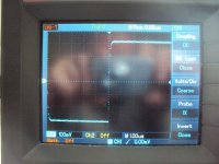
I have worked some further on the PEN circuit. I think i stroke a decent compromise. Configured that way gain is 15 x = 24dB. The circuit is fast. See the leading edge of the 100kHz square. -3dB is at 2.3MHz so my estimate was wrong. GB is 34.5MHz in this configuration. Not bad at all. I have not checked for noise and i have not listened yet though. For coupling i use 100uF Elna Silmik2. Noise can be brought down and gain can be raised by simply using more Fets in parallel.
Attachments
I have worked some further on the PEN circuit. I think i stroke a decent compromise. Configured that way gain is 15 x = 24dB. The circuit is fast. See the leading edge of the 100kHz square. -3dB is at 2.3MHz so my estimate was wrong. GB is 34.5MHz in this configuration. Not bad at all. I have not checked for noise and i have not listened yet though. For coupling i use 100uF Elna Silmik2. Noise can be brought down and gain can be raised by simply using more Fets in parallel.
I am very interested in this circuit but unfortunately I can not understand the way it works due to my lack of knowledge. Would you please explain it in ordinary language ?
Thank you Joachim.
It is very simple. One Fet is configured as a grounded gate circuit. That is comparable to a common base stage with a BJT. Fets are self biasing so this simplifies the circuit a lot. biasing a BJT or a conventional MOS is always trouble. The other Fets provides a constant current source. If the Fets are matched in IDss then the potential at the input is zero so no current flows into the cartridge. In fact i measured 30uV but this is low enough. Better matching then i did can improve on that but i found in praxis that even 0.1mV has no effect on the sound i can tell and does not destroy the cartridge at least when it is a Titan i like mine. Most of the current that flows in the Fets also flows in the Battery with the exception of the small current that flows into the 500kOhm resistors. This is a classical case of Kirchhoffs law. The input impedance of that circuit is low because the signal goes into the source of the Fet. It more or less short circuits the cartridge so the movement of the stone in the groove results in a current into the Fet. This current modulates the Gm of the Fet and results in a current over the 470 Ohm resistor that ultimately transfers that current into a voltage. PUHHH
Last edited:
[special=]%[/special]
Tankyou for that it is realy apreciated you are a real gentelman.
All I have is my ears and very litle experience with electronics-
That picture was posted somwhere else and enough to be loughed at and me been slapped around like litle Kid.
IMO Pilgrim Kit is definetley good, and I will give it a go,
still I like to learn things and make stuff the hard way so please carry on with all your hard work.
I think I speak for many here that are folowing what you are doing behind the curtains.
Sorry if I did not pick up this before I am at my Day Job at present.Your squarewave looks good though.
Tankyou for that it is realy apreciated you are a real gentelman.
All I have is my ears and very litle experience with electronics-
That picture was posted somwhere else and enough to be loughed at and me been slapped around like litle Kid.
IMO Pilgrim Kit is definetley good, and I will give it a go,
still I like to learn things and make stuff the hard way so please carry on with all your hard work.
I think I speak for many here that are folowing what you are doing behind the curtains.
It is very simple. One Fet is configured as a grounded gate circuit. That is comparable to a common base stage with a BJT. Fets are self biasing so this simplifies the circuit a lot. biasing a BJT or a conventional MOS is always trouble. The other Fets provides a constant current source. If the Fets are matched in IDss then the potential at the input is zero so no current flows into the cartridge. In fact i measured 30uV but this is low enough. Better matching then i did can improve on that but i found in praxis that even 0.1mV has no effect on the sound i can tell and does not destroy the cartridge at least when it is a Titan i like mine. Most of the current that flows in the Fets also flows in the Battery with the exception of the small current that flows into the 500kOhm resistors. This is a classical case of Kirchhoffs law. The input impedance of that circuit is low because the signal goes into the source of the Fet. It more or less short circuits the cartridge so the movement of the stone in the groove results in a current into the Fet. This current modulates the Gm of the Fet and results in a current over the 470 Ohm resistor that ultimately transfers that current into a voltage. PUHHH
Thank you so much... after all it is not that complicated
")
Hi Bksabath, just to let you know that I am a happy user of the Pilgham kit FPS, works beautifully! Here the three little issues I had:
- No bottom labels means it is easy to put in the OPA1632 the wrong way ;-((
- the footprint of the BF246 in the input current sources had D and S reversed
- the jumpers on the input signals (that are used to make the difference between Hi-Z and Low-Z) are quite close to the pins of the input JFETs so it is easy to accidentally short circuit there
Other than that it worked like a breeze. And it sounds fantastic!
just my two cents...
Tanks Hesener
I am waiting for Pumpkin and PSM bits and pieces.
I am using a very old Akay SS1 as pre at the moment and IMO I beter waith for Pumpkin before I do same critical listening.
Super Caps will be here in 4 to 5 weeks and was thinking how easy could be for one of those to kill someone...
And old drawings of my MC Phono and LAC charger are in a old/Broken hard drive
So I will have to strip down the lot and redraw and maybe make it beter (I am lerning a lot latley)
So busy busy
It will be a while till I get the Pilgam Kit but preaty shure it will be done.
In the mean time tanks realy realy apreciated
I hope you find the circuit diagram and can improve it.
Some time ago i published the JLH MC Pre-Pre. It was part of an article about symmetry in Audio in the early 90th i think. This schematic is one of the most simple symmetric schemas one can imagine short of the symmetric version of the PEN or the Hiraga. 20 years later i found a circuit by Samuel Groner that could be the son of those circuits and shows where we stand today. It is basically a symmetric differential input stage plus a second amplification stage and a buffer. It has a positive and negative input and an output so it is a discrete Operational Amplifier.
Some time ago i published the JLH MC Pre-Pre. It was part of an article about symmetry in Audio in the early 90th i think. This schematic is one of the most simple symmetric schemas one can imagine short of the symmetric version of the PEN or the Hiraga. 20 years later i found a circuit by Samuel Groner that could be the son of those circuits and shows where we stand today. It is basically a symmetric differential input stage plus a second amplification stage and a buffer. It has a positive and negative input and an output so it is a discrete Operational Amplifier.