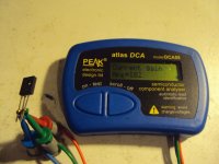
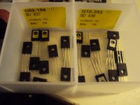
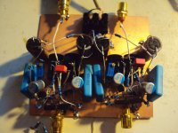
I have now prepared the input transistors. Why he chose those i can only reason about.
They seem to have a rather Low Rbb´because he gives the noise impedance even on the low current version as under 30 Ohm and that includes the feedback resistor of 18 Ohm.
So it must be 30 - 18 x 2 = 24 Ohm pro transistor under the current he chose. Rbb´must be even lower in fact because he runs them rather starved under modern view. Even in the "high" current version he runs them only on 1.1mA. I would use at least 5 to 10 x as much. The output stage on the other hand runs on a healthy 20mA plus ( on the high current version ) so there is potential for lower noise by raising the input stage current and using a lower impedance feedback loop. I have seen the same phenomenon on the original Hiraga Pre-Pre so both designer may have had the DENON DL103 on mind that limits the noise performance anyway because of the rather high self impedance. I have not measured it myself but i heard that the value of 40 Ohm given in the specs is not correct and it has around 20 Ohm instead what would be a good thing. For my 6 Ohm Titan this is sure not the optimum bias but as i said, i build it first as close to original spec that i can. These BD transistors are also rather slow. The Ft is only 3MHZ. That really surprised me but they are also very robust with 36W to burn.They where originally design for car audio by the way so this is funny. Hfe on the other hand is surprisingly high for a medium power device with around 130 on the PNP and 180 on the NPN. That minimizes offset of the direct coupled input. That can easily be beaten of cause by the special MC input stage devices by ROHM, Toshiba and Hitachi that have more the 500. They are not made any more and that is a pity. When i would do a modern version i would use Sanyo video transistors. They are also made by Fairchild and cost around 0.60 €. Concerning the schematic i think i found the latest version. That is the most logical to me and runs on plus-minus 5V.
Attachments
Homemodder, so you use a Szikley pair at the output. I use that sometime too. Did you had any stabilty problems? Anyway, i will build the circuit as is although with other transistors at the output because i do not have that old Motorola BCs. I have the correct input trannies though.
Lauret, when i look at the idle currents, 5V is much more logical.
Joachim, I apologize the right book is in fact sinclair and JLH also mentions the circuit in his own book. According to the text its correct that he states the use of a pair of dry cells but I think he intended them in series as it clearly also states that the design is optimised for 3 volts according to the text in sinclair s book which was written by JLH himself.
I indeed did have some stability problems with prototype the cure was simple, 5 pf caps accross Base Collector of each output cfp s. Also a single cap from output to ground worked just fine. Later with revised layout and proper PCB I didnt need any compensation at all. I used BC550 560 at inputs and slave of cfp s and 2sa1837 4793 and run the cfp s at 75ma but this is to power my sennheisers.
Looking forward to hearing your results, I havent found a circuit by JLH that didnt sound good, for him a circuit should measure at least reasonable and sound good too.
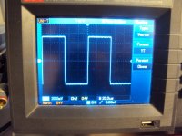
I build the JLH stage and i must say that i am impressed by the technical performance and the sound. Bandwidth is wide, -3dB at 10Hz and 1MHz. The 10kHz square wave is one of the best i have seen. Putting 50mV into the input did not clip the output. I made some small changes and simplifications and i will talk about that soon. Noise is around 0.7nV/qHz and commendably free of flicker and shot noise. Offset is trimmable to under 2mV and stays stable. I use a different trimming method then JLH but without changing the topology. That will be described too in due course. I did not select the BJTs in any way. I needed around 3 hours to build it and it worked right away. Even somebody that is not so experienced then me can build it over a weekend for minimal outlay. Recommended and lots of fun. Made my day.
The simplification i made was suggested by AS. The current limiter as he calls it is not necessary so i did not connect the 10kOhm resistors. I thought this is a kind of bias control but bias is rock stable without it. The DC offset i simply set by inserting a trimmer of 100 Ohm instead of the 80 Ohm resistors. After trimming i measured the value and it was 80.2 Ohm in one channel and 79.9 Ohm in the other. This makes the trimming kind of redundant. He also made the experience that the Elcaps can be unreliable so the Elcaps can be replaced with transdiodes with a 3dB noise penalty. The second stage could also be configured as a folded cascode for more speed, but ...... I just keep it as it is. I have a better idea. A balanced transimpedance input with nearly zero Ohm up to over 10Mhz. Even at 100MHz it simulates with only 21 Ohm. How that ?

This is the circuit i would build. I call it the JLH Homage Pre-Pre. I let it run on plus-minus 7V but that is not critical. I upped the idle currents quite a bit. 11mA in the input stage and 35mA in the output stage. I lowered the impedance of the feedback network. JLH uses 12 to 20 Ohm where i use 3.3 Ohm so i loose at least the noise of a 8.7 Ohm resistor. I inserted transdiodes instead of Elcaps. That makes the circuit DC coupled but in theory it is 3dB more noisy. I solve that problem by using ultra low noise transistors on high current. The specimen i chose are from Renesas ( Hitachi ). I think they are not made any more but production stopped only a short time ago so i see them here and there in quantity for around 0.5€ a piece. If you have them you can use similar Ultra Low Rbb´transistors from Toshiba or ROHM but they are virtually extinct or very expensive. As an alternative you can use medium power transistors from Sanyo, Fairchild or Zetex. Some of them are exceptional. I assume the noise performance of this circuit as 0.5nV/qHz so it is around 4dB more quiet. Shunting the transdiodes with 10000uF caps will lower the noise by an additional 3dB. In fact you could then take out the transdiodes again.
Attachments
I will measure that today. My precision meter had empty batteries but i got some now. With my normal meter it measures under 0.1mV. Theoretical it is 2,2mA / 150 = 15uA x 6 Ohm ( my Titan ) = 90uV in the original JLH design. In my design it is 22mA / 400 = 55uA x 6 = 330uV.
I know, that is a lot. You can look at it in two ways : the DC pushes the cartridge somewhat in one direction. That can be partly compensated by changing the tracking force. The other is, just relax and enjoy. What i know with many experiments i did with much more offset that the cartridge will not be harmed. If you can not life with that you can put in an offset cancelation. How that can be done i have shown before here. I will draw something for you that should work.
I know, that is a lot. You can look at it in two ways : the DC pushes the cartridge somewhat in one direction. That can be partly compensated by changing the tracking force. The other is, just relax and enjoy. What i know with many experiments i did with much more offset that the cartridge will not be harmed. If you can not life with that you can put in an offset cancelation. How that can be done i have shown before here. I will draw something for you that should work.
The other solution is a cap, see post 2482. JLH uses a 100uF elcap with a 1uF film bypass.
To prevent distortion in the bass i would use 1000uF. I tried Pannasonic FM and FC with good results. Niichicon Muse KZ is even better and the Elna Silmic 2 i can not differentiate from a film cap. Even a Pannasonic FM is good because the levels are so low. Now you have some options.
To prevent distortion in the bass i would use 1000uF. I tried Pannasonic FM and FC with good results. Niichicon Muse KZ is even better and the Elna Silmic 2 i can not differentiate from a film cap. Even a Pannasonic FM is good because the levels are so low. Now you have some options.
I noticed the problem with the elcaps too, using the circuit as headphone amp the distortion increased quite considerably at low frequencies with the recommended value of 100uf as given by JLH. The cure was 5600uf elcaps instead.
Nice results from just 4 transistors.
Semelab in the UK produced a second source equivalent of the 1085 and compl, RS electronics still had some the last time I checked, hopefully semelab they will produce more.
Nice results from just 4 transistors.
Semelab in the UK produced a second source equivalent of the 1085 and compl, RS electronics still had some the last time I checked, hopefully semelab they will produce more.