The Opamps should not affect noise much but the overload margin to drive the low impedance feedback network. One solution would be to give all Opamps a separate feedback resistor R26, R35. It could be anything from 100kOhm to 500kOhm i supose. Compensating caps C19, C20 could also be separated if that does not help.
No progress today as I had some trouble with the external power supply, and tonight I renovated my LP12 that hadn't seen any service in 22 years apparently. Wanted to go full symmetric today with the FPS but, well, .......
More next week, thank you joachim for your help!
More next week, thank you joachim for your help!
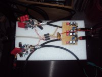
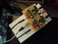
Some time ago i presented a simple BJT/MOSFet stage that could be used for the second stage of a phono amp. MIIB and i where paying a bit around with it and the performance of that circuit was found to be very good considering the small component count. I build one circuit to test it in the lab. It worked just fine but i never listened to it because i did not build a stereo set. That has being done now and i am pleased with the result. The pre-pre section i use at the moment is based on an older design from 2 years ago. It is a parallel symmetric folded cascode. I had some difficulty at the beginning to DC couple that circuit. I managed now to do that, even without a servo.
How does it sound ? Silky sweet and liquid. Maybe not as squeaky clean and tight as my best OP stages but very easy on the ear. Sibilance are not a problem at all. I have not found a conclusive explanation but some stages have problems with vocal sibilance and some don´t. Many stages pronounce the sharp "SSS" too much and it disturbs me much during listening. Not this stage. I heard stages that are subjectively more extended in the stratospheric highs or it seems so at last. This stages highs are there too but very well integrated into a broad midrange so the attention shifts down into the vocal and lead instrument range. I think this can be a good thing for many systems that suffer from sharpness or anemia. I measured the speed of this stage and it is very fast so measurably there is no treble loss. The subjective impression of sweetness and low fatigue can even come from the high speed of that circuit. I can certainly understand listeners that prefer simple discrete circuits over certain elaborate OPamp stages.
How does it sound ? Silky sweet and liquid. Maybe not as squeaky clean and tight as my best OP stages but very easy on the ear. Sibilance are not a problem at all. I have not found a conclusive explanation but some stages have problems with vocal sibilance and some don´t. Many stages pronounce the sharp "SSS" too much and it disturbs me much during listening. Not this stage. I heard stages that are subjectively more extended in the stratospheric highs or it seems so at last. This stages highs are there too but very well integrated into a broad midrange so the attention shifts down into the vocal and lead instrument range. I think this can be a good thing for many systems that suffer from sharpness or anemia. I measured the speed of this stage and it is very fast so measurably there is no treble loss. The subjective impression of sweetness and low fatigue can even come from the high speed of that circuit. I can certainly understand listeners that prefer simple discrete circuits over certain elaborate OPamp stages.
Attachments
When you watch the circuit a bit more closely it has some similarities with the symmetric Schlotzaur buffer so loading the input stage with a current mirror comes to mind. The mirror could also convenient set Vgs in the MOSFets. They differ quite a bit in this parameter.
Attachments
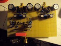
I felt a bit unsatisfied. I went back into the lab and there it was: the ground of the Pre-Pre was not connected to the second stage. Offset went down to less then 4V. The rest was possible to trim with the emitter resistors in the mirror. Ok, i floats around a bit. Therefore i use the output cap. A servo could be used of cause. Here are some pictures .... they do not upload i try again later
The circuit REALLY starts to fascinate me. Too bad. Where should i take all this time to fine tune it. What can also be done is a folded cascode as second stage. The circuit can then work non inverted. One other good thing with this solution is that the 2kOhm resistor that can be a source of noise is not used any more. The way i have drawn the circuit is suboptimal. The folded cascode can only swing so much voltage so there is some juggling to be done of how much dynamic range is available. I have of cause a better idea. I hope it does not get too much complicated.
Attachments
Sometimes the circuit diagram appears at page two. The reason is that i remove component names and they appear on page one. Sorry for that inconvenience. I try to be more careful.
By the way, i build the floating Fet version and it has the magic. I do not know if it is the current mirror or the Fets or both. I also bypassed the NOS trustworthy Wima 10uF MKT with a 19nF KP so any of this changes may have brought the benefit.
By the way, i build the floating Fet version and it has the magic. I do not know if it is the current mirror or the Fets or both. I also bypassed the NOS trustworthy Wima 10uF MKT with a 19nF KP so any of this changes may have brought the benefit.
Attachments
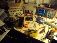
OK, found two more (ridiculous so I won't mention) errors and now the FPS is up and running. Adjusting the currents in the input stage took some time due to thermal settling, but it works!
The high power dissipation in the opamps is still there, however. Internet research and the other usual suspects did not reveal a good idea. The problem seems to be caused by the fact that the DC offset that any given opamp sees is unrelated to its own offset or corrective action, so it will "fight" it with all the DC gain it has available. That also explains why adjusting the offset is hopeless, since the trimpot position where it is correct is extremely small, and also drifting with time and temperature.
(Of course, capacitor coupling at the output would solve this, but this idea is so ridiculous for this circuit that I won't even mention it ;-)))
So, at this point I guess I will just live with this situation. As it stands, the opamps sit at about + or -2V or thereabouts, meaning the swing is reduced by 4Vpp, so the overload margin at this point is reduced to 16Vpp, a reduction of 2dB. Not that terrible.
Increasing the output resistors might help a little bit with reducing the power consumption, but the higher DC output voltage the opamps would settle to would further reduce the overload margin, I guess.
Any further ideas highly welcome!
The tube is actually needed as a reflex tube in a desktop monitor i am developing at the moment.
Good that the FPS works. We experienced the same. The Opamps get quite warm but the stage works fine nevertheless. Yours is working now too so am quite eager to know how it sounds.
My solution would be to mix the opamps in such a way so that both channels are the same.
Actually the offset they are showing is not a bad thing in many ways. It drives the output stages into class a. Another solution would be to use opamps with less input offset but the same GBW ( gain - bandwidth ) like the OPA277 or OPA1461. I mentioned that option in my original article. We then decided on the NE55534A out of the main reason that the kit should not be too expensive. Besides getting warm it works very well in this application because it is inverting ( no common mode distortion ) and it has low current noise for a bipolar. For example the LME49710 has 4 times more current noise but a bit less voltage noise. P.S. : I also tried the OP27 successfully. This is also a precision op with low offset.
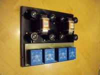
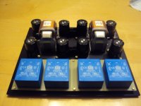
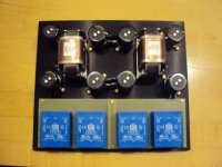
It must be over two years ago now. I fantasized with Salas about a really decent pre regulator for a phono stage. I am now in the good position that i am building a non compromise phono stage for a generous friend of mine. It will be called The Magnum Opus. Today i drilled the bottom board to fix the bigger components. The design is double mono. There are even 4 24VA spilt bobbin transformers in it. One for each voltage. The caps are Slit Foils, the diode bridges are Ixys Silicon Carbite. I use 4 in an arrangement that avoids direct current flow in the transformers. One of that bridges cost nearly 100,-$ so this is a real luxury. Common mode ckokes are fitted. This Lundahl LL2733 are not cheep ether. Snubber caps are Relcap Teflon. This guy is serious about sound. I used brass screws to fix the parts and i think the whole schebang came out nice, even a bit spectacular.