This time i am publishing only a fragment, I am into a thinking process to make a transimpedance phono stage with no DC into the cartridge without trimming or offset cancelation. The whole stage should be DC coupled again without trimming. The RIAA should be AIOG. Certain elements have being published by me before. Do you think what i think ....
Attachments
I got the MM stage of the FF2011 working. There where two bugs in the PSU so we could not make it work on FF2011. I am now locking into the MC input. There is a bias problem. The MM section sounds just fine. Very low noise and distortion and the rather prosaic LM49710 works very well with the slightly warm floating cascode buffer. Klaus, your layout work is beautiful.
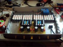
my FPS is working now, after a few more fixes (my problems, really....) Current consumption is around 210mA so I had to beef up my shunt regulators a little bit.
Measured the no-load current of 30 opamps and they deviated between 4.3mA and 4.6mA, with the occasional device at 4.9mA (using the schematic from the datasheet, voltage follower with input tied to ground, no load). That didnt explain the differences in temperature (today, 41°C ...70°C). Now I will try the suggestions from post #2381
Measured the no-load current of 30 opamps and they deviated between 4.3mA and 4.6mA, with the occasional device at 4.9mA (using the schematic from the datasheet, voltage follower with input tied to ground, no load). That didnt explain the differences in temperature (today, 41°C ...70°C). Now I will try the suggestions from post #2381
out of curiosity, I measured the DC output voltage of the opamps and it was all over the place (between -2V and +2V). Adding a trimpot to adjust the output offset of one of the "hot" opamps brought its output offset to around 0, and temperature down to normal. I will now be fitting offset adjustment to all 16 opamps, lets see what happens....
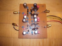
Some time ago i build a symmetric Schlotzaur Buffer as a alternative to out favorite Hawksford Buffer that needs 10 rare P-Channel Fets for a stereo pair in it´s full incarnation.
It is very fast, in simulation the resonance frequency is 190 MHz. I could not make it unity gain stable but i succeeded to make a version with a gain of 6dB. It is more like a high speed Opamp so it could be used for other purposes too. I will send out my prototype to Sam for listening evaluation. I can measure only to 20MHz because my DDS generator stops there. The buffer showed no sign of drop there. I build in a 1MHz input filter.
It is very fast, in simulation the resonance frequency is 190 MHz. I could not make it unity gain stable but i succeeded to make a version with a gain of 6dB. It is more like a high speed Opamp so it could be used for other purposes too. I will send out my prototype to Sam for listening evaluation. I can measure only to 20MHz because my DDS generator stops there. The buffer showed no sign of drop there. I build in a 1MHz input filter.


Hi,
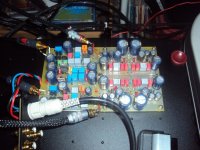
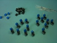
yes thats the circuit I used. Here is a picture of the implementation, a little crude but worked (well....).
With these trimpots, I could adjust every opamp to about zero offset at its output, however the other 3 then had drifted away... I was going in circles.... My reasoning for this is that each opamps offset is not correlated to the others and their adjustments, so whatever offset they "see" at the common output they will fight with all their DC gain, explaining why there is such a bipolar behaviour between them and also the adjustment point is extremely small, even with a 10turn trimmer.
I then changed the feedback structure, to have individual 47Ohm resistors from the inverting input to the output, and removing the common 47Ohm resistor. That reduced the DC levels to about + or -1V each output, and the power consumption reduced accordingly.
In fact, thats an old trick, pulling the output e.g. to the negative supply to bias the output stage of the opamps in class A. In this implementation this has happened "by accident" if I may say so, but that is only true up about 2V swing at the outputs of the NE5534s. I was thinking about adding a resistor to the negative supply, but that would introduce noise (from the supply) and distortion (from the resistor action), guess a current sink would be better. Beautiful symmetry gone however...
Still wondering though how that will affect the sound. Will the opamps be swinging around whatever DC offset they happen to have, or will there be a brutal crossover swing when the input amplitude reaches the offset value? Don't know, so I will be attempting to measure distortion at various amplitudes, and checking the output swing of the opamps to see what happens.
Alternative might be to remove 3 of the 4 opamps, then the problem is no longer there. However, the real beauty of the circuit is gone.... Wonder how noise would change.
Still havent done any listening tests of this beautiful circuit, because my turntable still needs to be modified for symmetric cables.... so much to do...
Attachments
Measured the output noise with one channel using the full set of opamps per side, the other with just one, and there was no significant difference in noise but that might just be my measurement setup. This circuit is very low noise so it is challenging my meager test equipment..... More tomorrow....