Rüdiger, this are the improvements i made : i put in two helper resistors. Because they would starve a bit only on the base current i feed them with aproximately 2mA of iddle current. I put in R3. When the same current flows in the left and right side of the mirror no current flows in R3. If there is a mismatch the resistor comes into action and provides differential feedback. i set it arbitrary to 100kOm. In praxis it has to be checked if that value is low enough. It reduces the impedance of the mirror some but it also provides matching and distortion cancelation so i think it is an improvement. I have seen parts of this circuit elsewhere but not implemented in total so i call it a Gerhard Mirror. I have drawn only one side and you have to scroll down a bit to see it. This circuit is much faster and lower in distortion then the simple cascoded mirror and gives an amasing gain in dynamics and slamm.
We had a report from member Stinius about a topological similarity with a drawing of his in another forum and a JG's originally attached above. We let JG know and he answered that he could not have seen it because he is not a member in that forum anyway. Non the less he felt it would be positive we pull his own drawing from the above post too.
Given the opportunity, please notice that people's drawings may not be copied without permission as they are, but any other drawing no matter similar topologically is belonging to the one who draws it, and he may circulate it at will. That's the official thing.
Similarities between circuit drawings from different people are not the concern of breaking any rule here and please don't report such to us in the future again.

Just for completeness i got the idea of the differential feedback resistors from Bob Cordell´s book " Designing Audio Power Amplifiers ", page 139. The rest was playing before a long time ago. There are other ways to reduce distortion in a current mirror that do not require this resistors. The main problem is the limited output resistance. A mirror can be made that has limited, infinite and even negative output impedance. Stinius, you are attacking the wrong person. I am here to put information in this world.
Members obviously can claim ideas and ask for public credit and be answered by clarification from other members. That is something different from expecting DIYA to be pulling content of drawings belonging to others without their consent. In this case we had your consent.
Your circuit looked certainly very orderly to me Rüdiger. You found your MPP nirvana for sure.
I am currently running a stage with a Salas Shunt too. Yes, sure, it makes batteries obsolete but i whould not say it sounds worse with batteries. I call that progress. Batterie management is no fun most of the time. I have my LFD Batterie stage the third time in England for repair.
I am currently running a stage with a Salas Shunt too. Yes, sure, it makes batteries obsolete but i whould not say it sounds worse with batteries. I call that progress. Batterie management is no fun most of the time. I have my LFD Batterie stage the third time in England for repair.
It had to happen. After much thought i am back on the MPP thread. Mostly because i got a lot of ecouragement from members and second because several people are building some of my designs and the PM box is flowing over so this is a much better place to discuss and help.
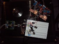
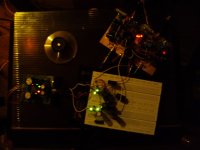
One thing i designed recently is a buffer. It is ready, works well and there are some test PCbs that need some changes. I had a problem with oscilation, that thing is damn fast, but that is solved now. I also designed my first PSU. Usually i am using the LC Audio Low Noise PSU, Salas Shunts or batteries but it was time to design something myself. Actually there was not much to design. I simply decided on a 3 stage topology where i use well known techniques in cascade. First are LM regulators. Then comes a discrete circuit that has a constant current source supplying a TL431 that is noise reduced. That voltage is low pass filtered and taken to a pass transistor. It´s a kind of voltage regulator with a cap multiplier. Then comes a passive C-L-C combination or a Keentoken cap multiplier. I build it this time on a perf board and got it working in two days. I prefer the result to the lead acid batteries i used. It sounds more dymamic and robust without loss of fine details.
One thing i designed recently is a buffer. It is ready, works well and there are some test PCbs that need some changes. I had a problem with oscilation, that thing is damn fast, but that is solved now. I also designed my first PSU. Usually i am using the LC Audio Low Noise PSU, Salas Shunts or batteries but it was time to design something myself. Actually there was not much to design. I simply decided on a 3 stage topology where i use well known techniques in cascade. First are LM regulators. Then comes a discrete circuit that has a constant current source supplying a TL431 that is noise reduced. That voltage is low pass filtered and taken to a pass transistor. It´s a kind of voltage regulator with a cap multiplier. Then comes a passive C-L-C combination or a Keentoken cap multiplier. I build it this time on a perf board and got it working in two days. I prefer the result to the lead acid batteries i used. It sounds more dymamic and robust without loss of fine details.
Attachments
Oh please, I don't "look a 'gift horse' in the mouth". It is a reconditioned Helikon SL. Wanted one for years, even if it is NOW last years model. You must have some idea that I make a serious living in audio. You should know it is almost impossible to do so. I cannot afford my own designs, how could I possibly afford an uptown phono cartridge like you have?
Well the Helikon SL is very good to test your phono amps for low noise because of the low output. Usually when they come back from Mishima they sound better then they ever had because he puts in all his new knowlage on the way. My Titan i after refurbish sounds much better then it ever had. Concerning income mine is 1/10th then i made in the 90th when i sold speakers by the truckload. Yes, this High End busyness got tough so i am quite displeased that people like us that really try to improve sound get more often acused to be greedy. Anyway, i am a more happy person then i was 10years ago traveling the globe without rest and no time to develop.
Klaus and me re-experience diy in the moment. We are getting inspired from the ideas and designs that are posted by you, Joachim .
My little diy career started in autum 89, when I received my first issue of Audio Amateur.
Ups and downs, enthusiasm, dissapointment and lack of interest, came up and left through the last 20 years.
diyaudio.com, the german AAA forum, and the small frickelfest.com side are my favorites, but all of diy audio lives from people like Papa, ZenMod, John Curl,
syn08, Joachim Gerhard, Juma, AndrewT, Scott Wurzer, always online Salas, Planet10, etc. etc.
Thanks to all the people who are contributing, and thanks to all the people who are participating. To all the people who organize GB, simulations, etc. etc.
Welcome back Joachim, and stay!
Thanks Sam. See you on saturday and i bring a phonostage with my own PSU. The PSU is rather simple but works to my satisfaction. For me it sounds better then lead acid batteries even when i buffer them with RC filters and common mode chokes.
It will be intersting to listen to your 3 versions of the FF2010 lineamp. Thanks that you did not give up on this.
It will be intersting to listen to your 3 versions of the FF2010 lineamp. Thanks that you did not give up on this.
I am currently working on a new high speed headphone amp that can also drive high effiency loodspeakers or computer monitors. But first see this nice historical video of the making of the RCA Living Stereo records.
Sound And The Story : Handy (Jam) Organization : Free Download & Streaming : Internet Archive
Sound And The Story : Handy (Jam) Organization : Free Download & Streaming : Internet Archive
Yes, they did a major efford in 1956. I was born in 1957, so right at the start of the commercial available stereo record. No wounder i am so attracted by vinyl.
I have made a basic circuit for my new headphone amp. My old headphone amp was published here. It is basically an input buffer, an inverting Opamp and a diamond buffer at the output. I published it here some time ago. I sounds good but i miss something. It could sound more dramatic and with more slam although i run it in class A with more the 50mA standing current. Actually my AKG K701 is not an easy load at all. I also miss the last bit in treble resolution. It came already clear to me that the diomond buffer can be aproved on. First i made a Fet-Bipolar buffer and then the Fet-Hawksford-Cascode buffer and both sounded better then the diamond buffer. I think with the Hawksford buffer i reached my nirvana so far. ( is there any intermediate nirvana ? ).
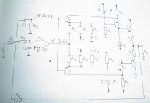
What i trying now is a circuit i found in Tietze-Schenk 6. edition, page 508. Thanks to AS audio to send me this historic sample. It is called " Breitband-Leistungsverstärker". In english that translates into "Wideband-Poweramplifier". The idea is a work of genius i thing and very advanced for the time of publishing in 1983. There is an low frequency path and there is a high frequency path. The low frequency path goes over an Opamp and the high frequency path goes over a discrete folded cacode amplifier. At the output is a parallel symmetric emitter follower and the gain is controled with the Opamp in shunt feedback. The disadvantage is a quite low input impedance if you want the lowest noise so when your driving CD player or vinyl playback system can not drive say 2kOhm an input buffer is needed. That could of cause be the Hawksford. I will publish the fundamental circuit in some hours. It is still an alpha so i did not build it so far and component values are not all dimensioned and may change in value.
I have made a basic circuit for my new headphone amp. My old headphone amp was published here. It is basically an input buffer, an inverting Opamp and a diamond buffer at the output. I published it here some time ago. I sounds good but i miss something. It could sound more dramatic and with more slam although i run it in class A with more the 50mA standing current. Actually my AKG K701 is not an easy load at all. I also miss the last bit in treble resolution. It came already clear to me that the diomond buffer can be aproved on. First i made a Fet-Bipolar buffer and then the Fet-Hawksford-Cascode buffer and both sounded better then the diamond buffer. I think with the Hawksford buffer i reached my nirvana so far. ( is there any intermediate nirvana ? ).
What i trying now is a circuit i found in Tietze-Schenk 6. edition, page 508. Thanks to AS audio to send me this historic sample. It is called " Breitband-Leistungsverstärker". In english that translates into "Wideband-Poweramplifier". The idea is a work of genius i thing and very advanced for the time of publishing in 1983. There is an low frequency path and there is a high frequency path. The low frequency path goes over an Opamp and the high frequency path goes over a discrete folded cacode amplifier. At the output is a parallel symmetric emitter follower and the gain is controled with the Opamp in shunt feedback. The disadvantage is a quite low input impedance if you want the lowest noise so when your driving CD player or vinyl playback system can not drive say 2kOhm an input buffer is needed. That could of cause be the Hawksford. I will publish the fundamental circuit in some hours. It is still an alpha so i did not build it so far and component values are not all dimensioned and may change in value.
Here is the concept of the BLV ( Breitband-Leistungs-Verstärker). Let´s see out of what black hole somebody comes that has invented it and has all this done before.")
Feedbeside amplifier?
US patent 4,132,958
jan didden