You have seen here a phonostage for Martina Schöner. It needs exactly + - 10V and i plan to compare the Hynotize to the LC Audio Low Noise Supply i am usually using.
See the circuit for one channel.
Yep, but a Hypno to have closely tracking +/- Vout and same PSRR you need to read the first post in that thread. There is a dedicated twist that works well only for the audio portion on it that you have to remedy, see a pic with some leg trick in a positive side Jfet there. You can also try run it hotter than July and bypass the LEDS with 0.22uF PP instead of lytics for best sonics. It also does not have remote sensing* and its just V1, but will give a hint to its younger family performance. You can cut out excess board if you will keep it as a reg only in the end, like in that example.
*Use very short thick cabling from Hypno to phono, make them close neighbors.
I asume it draws about 60mA per chanel. Can the Hypnotize supply that? Do i have to cool the Mosfets ?
For both rails?
With 68//68R set resistors it runs as much per rail. You would need 120-200mA per rail even for it does better waking up the Mosfets. See the Vdrop on its Iset resistors and down value accordingly. Around 8.2-10R 5W should do it for 0.2A+/-. Sink it. In its native mode for its on board audio is running low and without sinks. I don't think it can cater that way for your needs.
I was asked how much gain that circuit has. Well if i asume that the cascodes just put thruw the gain of the input stage and the the mirrors are high impedance enough we could simplyfy and say that the gain at 1kHz is Gm x RL. See Sigurd Ruschkovski´s simulation of the input impedance of the RIAA network used. It has around 9.8kOhm @ 1kHz and the Fets are running at slightly under Idss. That makes the equation 88mS x 9.8kOhm and that is 0.088 x 9800 = 862,4 . That is slightly under 60dB and this seems to be about right. To raise the gain the impedance of the RIAA network has to be raised
or the amount of Fets has to be doubled for example for 6dB more gain. The BC550C and BC560C are not very happy at 32mA idle so i whould use something more robust here. Be aware though that higher power trannies often have much less Hfe so the impedance of the mirror goes down. Now my choices get more clear i think.
or the amount of Fets has to be doubled for example for 6dB more gain. The BC550C and BC560C are not very happy at 32mA idle so i whould use something more robust here. Be aware though that higher power trannies often have much less Hfe so the impedance of the mirror goes down. Now my choices get more clear i think.
Attachments
i use that stage directly into my tube poweramp that has a 10kOhm potmeter at the input.
I have not measured the gain of the poweramp yet but i get a lot of volume that way even with the Mini MPL BWBA that has 86dB sensitivity so i asume that my poweramp has more gain then usual.
Can one board of Hynotize supply both channels ? Your answer was not totally clear about that. I have another empty board so i could try double Mono if one board is not enough. Could you post a circuit with all the changes i have to make ? Sorry, that gives you some work to do but i am teribly busy at the moment. My buffer is still not working and Martina comes soon and i have not finshed the complicated cabling. That is parallel to my profesional things i have to do to survive.
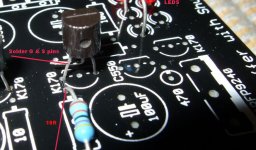
Step 1. See that picture I attach. Locate the K170 pictured near the 10R on the positive reg side (where IRFP9240s are associated). Cut mid leg board level, lift, solder as in photo. Don't change anything on the negative side.
Step 2. Use 33//33R 1W resistors where it says 68//68. That will run approximately 120mA per rail. Check the heat on Mosfets when feeding the phono, should still be comfortable, else use small sinks on each one. Don't power it up without the phono connected if not heatsinked. Keep them reg and phono intimate with short wiring.
That will be the fastest since you are busy. Just setting it right with no or minimum sinking.
Attachments
Well that counts for less then 50mA per channel but i wanted to go conservative.
Yes, but I also saw 16V 3300uF filter caps on your board. That is marginal. What kind of trafo VAC secondary are you planning? The Hypno will still regulate well with 15V rectified DCin but take care for overshoot & longevity.
You should get around +/- 16.5VDC on those caps then if trafo is winded precisely. If your caps are OK too, I leave you work. Good luck with that combo soundwise, hope it will prove synergistic. If your 5 leds rows are near for Vf and those near 10R located K170s near for idss, you will get a closely tracking +/- Vout too. If you have small clip on heatsinks or those small ones for LM317 with a screw hole that need no board fix, use them for long term peace of mind.
I think i will use two 100 Ohm resistors. One on each rail. I will get it working tonight.
Another question. Before the phono i have two common mode chokes with 100mH. 1.5 Ohm. Should i pull them out ? On the phonoboard i have around 2000uF caps on each line in each phono. Can i keep then in ? I know, i sound like a newbee. I just whould like to avoid trouble to make that process painless. I am really on a tight schedule at the moment. The most anoying but important part is that i have to come up with a detailed busyness plan to finance a new enterprise and this is absolutely not my forte.
Anyway, what i am doing here is important for me beacause it is so much fun and that keeps my mood up.
No inductance or series resistance between this reg and phono. Save them for elsewhere. Inductance will make it oscillate, resistance will vaporize reg's inherent minimal Zo. Avoid the local big caps to ground too. Redundant, just imposing signature and mixing very high in frequency without the coils that used to be there.
100 Ohm dummy load per rail gets you shunting to ground near the CCS setting, the shunt element will feel much cooler that it will be when the phono is fed. If the CCS Mosfets Vgs or 3 leds Vf are not convenient and it sets around 100mA for real with those 33/33R, its possible them dummies eat all available mA and the reg starves testing cookoo.") Don't you have some extra resistance to add on those dummies so to be sure there is enough current remaining in the reg?
Don't you have some extra resistance to add on those dummies so to be sure there is enough current remaining in the reg?
P.S. You don't sound like a newbie, you sound like busy.
100 Ohm dummy load per rail gets you shunting to ground near the CCS setting, the shunt element will feel much cooler that it will be when the phono is fed. If the CCS Mosfets Vgs or 3 leds Vf are not convenient and it sets around 100mA for real with those 33/33R, its possible them dummies eat all available mA and the reg starves testing cookoo.
Don't you have some extra resistance to add on those dummies so to be sure there is enough current remaining in the reg?P.S. You don't sound like a newbie, you sound like busy.
It will be the same draw with 200R per rail. You said 50mA per rail for 2 channels, 100mA total for 2 channels & all rails, right? Please confirm. We can't afford a misunderstanding at this point, else it will set you back for available time.
Although a Hypno board carries the most humble of this regs family, here is how yours with the settings and load you put, simulates in LT Spice for Zo. Use short thick wiring so you compromise it the least possible since there is no Kelvin connection ability in this board. It was made to be used for the DCB1 part on it within cm distance. Y axis is 1 Ohm top.
Although a Hypno board carries the most humble of this regs family, here is how yours with the settings and load you put, simulates in LT Spice for Zo. Use short thick wiring so you compromise it the least possible since there is no Kelvin connection ability in this board. It was made to be used for the DCB1 part on it within cm distance. Y axis is 1 Ohm top.