Here is the data sheet :
TQ2-12V pdf, TQ2-12V description, TQ2-12V datasheets, TQ2-12V view ::: ALLDATASHEET :::
they use gold plated silver contacts
TQ2-12V pdf, TQ2-12V description, TQ2-12V datasheets, TQ2-12V view ::: ALLDATASHEET :::
they use gold plated silver contacts
Now, not to push on anyone's feelings, but we used equal or better relays more than 40 years ago, and we used similar parts in the JC-80, starting in 1982. We use a hermetically sealed version of this part in the new project. This is very old, tried and true, and just OK. Silver on Silver switches are better.
Hermetically sealed, that should be the best of cause because silver is the best conductor. In open air silver develops a sulfur contamination very quick,. In fact sulfur contamination gets worse every year because air polution is still rising. i heard that labs that are researching air contamination use that effect to test polution, Contrary to popular beleave this world still gets more poluted every minute.
Here is the data sheet :
TQ2-12V pdf, TQ2-12V description, TQ2-12V datasheets, TQ2-12V view ::: ALLDATASHEET :::
they use gold plated silver contacts
Nice relays. I tend to use Omron relays, which are largely equivalent to the Nais.
One thing that still intrigues me is the spec for 'minimum current/voltage'. Both the Nais and Omrons spec 10uA/10mV here. What exactly is the meaning of this spec?
Nais doesn't detail it, Omron calls it 'failure rate' (for connection?).
It is tested to the limit of 100 ohms contact resistance max.
Now, in audio, signal levels will routinely be below 10uA/10mV. Would that mean that these relays cannot be counted on for their 'official' low contact resistance of 30 or 50 milliohms? It could make a big difference in, say, a stepped attenuator whether the contact resistance is 50 milliohms or 50 ohms!
jd
We have used the Nais TQ5-TQ12 and Omron equivalents on the DCB1's signal inputs/outputs with no apparent resolution penalty.
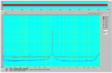
In the first picture there is a Hypnotize build with one output relay. The second one comes from a Mezmerize build measurement with Nais TQ both on input and output. If they can pass a smidgen of 3rd Harmonic to be displayed on the -130dB grass, I guess their contacts are OK?
In the first picture there is a Hypnotize build with one output relay. The second one comes from a Mezmerize build measurement with Nais TQ both on input and output. If they can pass a smidgen of 3rd Harmonic to be displayed on the -130dB grass, I guess their contacts are OK?
Attachments
We have used the Nais TQ5-TQ12 and Omron equivalents on the DCB1's signal inputs/outputs with no apparent resolution penalty.
In the first picture there is a Hypnotize build with one output relay. The second one comes from a Mezmerize build measurement with Nais TQ both on input and output. If they can pass a smidgen of 3rd Harmonic to be displayed on the -130dB grass, I guess their contacts are OK?
Well, the 'smidgen of 3rd' is of course part of the total signal which maybe on the order of 100's of mV or even a volt?
Even AP uses these types of relays in their analyzers, so yes they perform well.
But as I said, I'm not sure what the significance is of that spec. It is there, it is tested so it should mean something.
Anybody can shed any light on this?
jd
First P2 and P3 are adjusted to 180 Ohm including the drain resistor.
Then the input Fets are grounded and P1 is lifted from ground.
Then adjust P1 for zerro offset from A to ground.
Then wire everything back. Adjust P2 for lowest offset at the output and then fine adjust offset with P4.
I hope this is clear now. The nice thing with this trimming is that lowest offset should also come with lowest distortion in this schematic but i will measure it and look whats happening too.
Well, the 'smidgen of 3rd' is of course part of the total signal which maybe on the order of 100's of mV or even a volt?
jd
Forgot to tell that If there is digital zero for input, hence no signal output, the noise floor does not change shape or -dB level, remains like when passing the 1kHz at hundreds of mV to 1 or 2V if that can show something, towards your query.
I am still working on a BJT version of the Discreet INA, theoretical that is because my fried board is not working still. I got the input stages working but not the rest. I substituted a lot of elcaps but that board is crowded so i started to build a new one from scratch. The circuit shown should allow DC coupling of the input. Bias is taken from output of OP1, OP2. The OPA134 servo allows finer adjustment with a 100kOhm trimmer.
I am also building a high quality headphone amp to listen to pasive components and make listening posible late at night when the family is sleeping.
i started to work on an rbb measurement setup and i am planning a RIAA encoder.
I am also building a high quality headphone amp to listen to pasive components and make listening posible late at night when the family is sleeping.
i started to work on an rbb measurement setup and i am planning a RIAA encoder.
About relais ( I saw you were talking about): a lot of good relais are no more available these days, a pity. This has to do with RoHs and WEEE here in Europe. But since most younger people nowadays listening to mp3 sounds only, it may not longer be necessary to deliver good sounding parts. Btw. Fraunhofer Institute (mp3 inventor) says that's nothing wrong with mp3 sound qualitity. I did not knew that my ears are so bad, because of I do not like the wimpy, bloodless mp3 sound ;-)
From the current available relais types a nice sounding one is the Panasonic ASX (e.g. the ASX20012). Min. switching capacity is as low as 10µA and 1mV (instead of the standard 10mV). Additional I found out that relais with particularly low thermoelectric voltage and thermal electromotive force sounded better to my ears. Pickering switches are making such devices as well, but they do not last very long ;-)
From the current available relais types a nice sounding one is the Panasonic ASX (e.g. the ASX20012). Min. switching capacity is as low as 10µA and 1mV (instead of the standard 10mV). Additional I found out that relais with particularly low thermoelectric voltage and thermal electromotive force sounded better to my ears. Pickering switches are making such devices as well, but they do not last very long ;-)
I started to build a headphone amp to make listening late at night posible and also to listen to passive components. Because i am also a hobby musician i own a lot of different phones from AKG and Sennheiser.
I have the HD280pro, AKG501 modified and AKG701 for example.
My main phone is the AKG701. It has quite a low impedance so I will use a diamond buffer
with ca.30mA class A as output stage. It can swing 50mW class A into the 60 Ohm AKG.
The buffer is a more or less clasical design with improvements to the current source that are similar to the High Z MPP i posted lately. A Fet constant current source feeds a green Led. The output is lowpass filtered by a cap and resistor to the bias transitor.
That arangement is very stable and after trimming offset with P1 it stays under 0.1mV.
As input buffer i use the PSG buffer with offset trim and i am still working on the voltage amplifying stage. I am trying to build a kind of I/U converter with current mirrors so the whole amp is global feedback free.
Attachments
New Headphone thread.
Hi Joachim,
I think it's better to start a new thread with your Headphone amp.
It would be a pity to talk about this headphone amp in your own MPP thread which is a tremendous phono amp.
BTW this is a similar amp but only with a different front (read: no led's) and output 2x.
Best regards,
Audiofanatic")
Hi Joachim,
I think it's better to start a new thread with your Headphone amp.
It would be a pity to talk about this headphone amp in your own MPP thread which is a tremendous phono amp.
BTW this is a similar amp but only with a different front (read: no led's) and output 2x.
Best regards,
Audiofanatic
Attachments
I have seen that topology. I found it when i googled "Diamond Buffer". It should work as well. The cap-resistor lowpass i am using should work with that too. You loose a little bias voltage but i use BC550C/BC560C here that have current gain over 600 in my samples. I really think this little project is too small for it´s own thread and i already opened another worm of cans : "MPL", My Privat Speaker.
Anyway, i decided on a different topology. An OP amp is now doing the work in shunt mode. This way i can also listen to OP amps but i fear that even the NE5534 is good enough because in shunt feedback i only use the basic transfer linearity that is very good in most. Some with FET input have trouble there but i expect no enlightenment.
One channel of the Headamp is already working and noise is not audible.
I will build the other channel and then report.
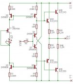
Here comes the schematic but i have no plans to optimise it much any further.
Of cause i can play with iddle current and thinks like that but i think the way i made it is just fine for my pupose. If questions arise i will of cause answer.
P.S. : the amp is phase inverting so i may cut the leads of one of my phones and seperate the grounds.
P.P.S. : i use a 10kOhm pot on the input to get good speed with the Fet. I nulled the offset of the output stage first with the 1kOhm trimmer and nulled the compleet amp with the 100 Ohm trimmer. Offset is very stable and under 1mV.
Anyway, i decided on a different topology. An OP amp is now doing the work in shunt mode. This way i can also listen to OP amps but i fear that even the NE5534 is good enough because in shunt feedback i only use the basic transfer linearity that is very good in most. Some with FET input have trouble there but i expect no enlightenment.
One channel of the Headamp is already working and noise is not audible.
I will build the other channel and then report.
Here comes the schematic but i have no plans to optimise it much any further.
Of cause i can play with iddle current and thinks like that but i think the way i made it is just fine for my pupose. If questions arise i will of cause answer.
P.S. : the amp is phase inverting so i may cut the leads of one of my phones and seperate the grounds.
P.P.S. : i use a 10kOhm pot on the input to get good speed with the Fet. I nulled the offset of the output stage first with the 1kOhm trimmer and nulled the compleet amp with the 100 Ohm trimmer. Offset is very stable and under 1mV.
Attachments
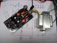
The Headphone Amp is up and running.
It is dead quiet and PSU rejection is very good. I ran it on 8.5V negative and 12.5V positive without trouble.
The sound is extremely analytic so flaws in the program material stand out quite uncomfortable. I am surprised how much reverb is used on most productions. Analog recordings show frequency modulation and noise in high measure. Digital recordings with old A-D converters are not unproblematic too because a lot of granularity is audible. All in all this type of listening gives me new information.
When the recording is good the result is intense.
If i whould do a commercial version i whould set the amp on a servo and substitude the Fet buffer with an Opamp. The Fet current source could simply replaced by a 10 to 20kOhm resistor without much compromise. That way no adjustment is necessary.
If the source impedance whould be known, a compensation resistor could be added in the buffer.
Attachments
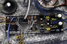
I got a decent Digital Camera so tomorrow i will post some picturs of what i build recently.
I get a scope and function generator for my homelab so i will be able to post some measurements without the need of my professional lab.
That stuff has got so cheep that even i can afford it.
I get a scope and function generator for my homelab so i will be able to post some measurements without the need of my professional lab.
That stuff has got so cheep that even i can afford it.