Onvinyl i thought about your interesting circuit and came with the following idea:
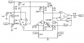
what about a balanced Instrumentation Amplifier ? I have to think about the feedback and where to put the RIIA (should be symmetrical too) but here is the concept. Do not take the values and the components serious yet. It is just the principle.
what about a balanced Instrumentation Amplifier ? I have to think about the feedback and where to put the RIIA (should be symmetrical too) but here is the concept. Do not take the values and the components serious yet. It is just the principle.
Attachments
Hi Joachim,
nice you taking that litte circuit further.
Don't the inputs of the lower opamp need to be reversed? Ah, not sure.
I have some objections: It will be a pain to control it dc-wise. As I said I get some tens of millivolt at the output if no servo is present (by tweaking the drain resistors). So you will have some more at the input of the instrumention amp, that will again amplify the already high offset and glue to one rail.
The feedback loop is quite big now.
Are there any suitable monolithic instrumentation opamps on the market that might work here? Would be a great benefit layoutwise.
I have no idea for an elegant placement of the riaa network yet.
Rüdiger
Can you please explain why it has poor noise, poor inpt impedance, poor offset - and why these, other than noise, and to a very small degree, offset, are important in a MC phonostage?
You know nobody can debate the "sounds good" argument. You are running a business and therefore you are supposed to make your customers happy, which I am sure this design does. However, there is potentially a significant gap between (say) what customers really like and what customer are told to like...
While I fundamentally disagree with the whole "NFB bad" concept which, to me, is only a marketing catch and ultimately only proves how poor the subjective evaluation criteria are, I'm not going to debate this option. Rather than this, here are my concerns:
1. Noise. I already shoved that those input resistors are a compromise that I would really hate doing. I don't really understand how this non-feedback stage can oscillate, though, at 30MHz. I'm pretty sure it's a layout problem.
Assuming SY is right and this thing has a total of 0.8nV/rtHz (although by looking at the SSM datasheet, and also considering the current noise, this seems very marginal), I would certainly not buy this product, in particular for a (as you said) 100uV cartridge.
0.8nV/rtHz is about 0.1uV RMS in the audio band. You would of course note that the S/N re: 0.1mV (unweighted) for this amp, including a 10ohm MC cartridge is only 57dB. This will make the hiss in the speakers (not very sensitive) clearly audible. I personally can't stand anything under 63-64dB re: 0.1mV (unweighted) - but perhaps your average customer is way less picky than yours truly.
In all the above I did not consider the noise impact of Rgain, which can only make things worse.
2. Input impedance. 1Kohm seems to be high, but I'm strongly advocating a maximum flexibility in input impedance. 47Kohm should be the default, anything lower should be switchable (and also capacitive loading). Make no mistake, this is achievable with bipolars. But perhaps your customers are told that 1Kohm (or less) loading for a MC is anything they will ever need?
3. Offset. Let's take a look at the MAT02 datasheet. This pair is matched to 0.2mV. You would of course accept that this (mis)match drops straight on the MC coil. For a 10ohm DC impedance, this maps to a DC coil current of 20uA. Is this a lot? I don't know, but certainly the DC voltage drop is twice the cartridge AC voltage, which to me doesn't sound right. If you would mention 20uA through an MC cartridge, lots of audiophiles will freak out. Are your customers aware of this current level through their expensive Lyra or Koetsu?
The solution is to use some sort of offset trimming and taking advantage of the pairs excellent tempco match. Even the simplest Hiraga head amp has such trimming, do you really think it's a good idea to skip it?
BTW, it is possible to trim the input bias current of a bipolar complementary pair to under 50nA.
In another message you mentioned MAT02, which has only 50uV offset, mapping to 5uA through the cartridge. Still two orders of magnitude of what one can get through trimming, and still a 50% DC level, compared to the AC voltage. Unfortunately, the 50uV offset comes (according to the datasheet) with some noise penalty.
4. Tube cascode. I still have to understand (from an engineering perspective) why anything but a tube is not as good in a cascode stage. You don't like a MOSFET, any reasons why? You can also use a high voltage bipolar, 200V devices cost pennies. But as I said, if the decision to use a tube was based on the "good sound" then so be it. I hope it was not a marketing driven decision, based on the need to defend a brand, or to take advantage of the "tubes are good" rap. Anyway, if there's some objective performance driving the tube use here, then I am sure the performance can be matched by using SS devices only. BTW, have you estimated how much the tubes heat is affecting the overall noise (because I assume the tubes have to be in the proximity of the SSM pair)?
On top of my head, I don't know how much is the tube cascode PSRR, but certainly the power supply noise and AC performance will have a huge impact on this MC stage overall performance. I see you are feeding the filaments in CC using a LM317, which is probably very good for the PCC series. Could you shed some light about the power supply?
What made me think that this design is purely subjective performance driven (and you somehow confirmed this in a subsequent message) is that the same level of objective performance (and avoid all the above issues) can easily be reached with two low noise JFETs cascoded with a bipolar device. Low noise n channel JFET devices are still available in full production.
Last edited:
It's going up against Joachim's best, how about sending one of yours over and there can be a real shootout?
This would be a quite expensive endeavour. I would love though to bring my non-commercial stuff against any commercial products available today, in a controlled listening test.
Not gonna happen anytime soon, nobody is ready to finance such an experiment.
Rüdiger. i would give one Reiner Sound reissue LP to the first that finds out which way around the second op am goes.
The intrumentation amp that comes to mind is the INA163. I can be beat with a "pseudo discreet" design if you use Charcroft naked foil resistors and specify them to at least 0.01% tolerance. They have zero temperature dependence over a very big range. The instrumentation amp should be no problem DC wise. The major advantage of the Instrumentation amp is DC precission. One idea whould be to use "short" feedback after the first two opamps to their fitting node and then add the differential summing amp without including it in that first loop.
If i had more time !
To syn08 : to my knowlage Allen has not heard my best Phonostage yet so i wonder why he is so shure about the outcome. Maybe we could sometimes in the future meet in the Americas to do the shoutout. I have good relations to an Audiophile Society in San Francisco so we could ask thoose guys to make a blind test. I already know the outcome : 33 %, 33%, 33% and 1% for god. That is always the outcome with double blind ABX and the NAD whould not do much worse ether. It simply can not be resolved in any scientific honorable way and the only option we have is to quote your favourite subjectivist John Curl : "please let me play in my box of sand and then i let you play in your box of sand" maybe not exactly what he said but that was what i understood.
I already know the outcome : 33 %, 33%, 33% and 1% for god. That is always the outcome with double blind ABX.
That's likely to happen. Which, to me, proves how much (or how little
") ) is our hearing able to figure out.
) is our hearing able to figure out.We are happy with the 0.1% distortions of an open loop circuit, but then it comes (sorry, but I can't resist mentioning after looking at Allen's schematic) to "non-magnetic resistors" like it would really make a difference to any decent, regular metal film resistors, other than just another marketing catch good for the Stereophile crowd.
Now you got me !
If you have finished your new stage i will etch a board if you allow and build one with my part choices. i will send that stage to you after i have run it in and i am shure it performs correctly. if you do not hear a difference, forget about the parts issue. Of cause you should measure it too if it performs to your standarts because i know that small LINEAR differences like tiny variations in frequency response can have a surprisingly high effect on sound. My conclusion is : first toplogy and values and then parts choices. it is poor praxis in the high end that flawed designs (specially loudspeakers that claim high end although the on axis response is + - 10dB) get outfitted with extremely expensive components and hardware and would not pass any fidelity test in a professional recording or broadcast studio. Still people are thrilled by the performance and wax lyrically about component changes. I see component coices as neccesarry fine tuning because small flaws can get really anoying over long term use. immagine you eat your favourite dinner each day, it should be better really good.
If you have finished your new stage i will etch a board if you allow and build one with my part choices. i will send that stage to you after i have run it in and i am shure it performs correctly. if you do not hear a difference, forget about the parts issue. Of cause you should measure it too if it performs to your standarts because i know that small LINEAR differences like tiny variations in frequency response can have a surprisingly high effect on sound. My conclusion is : first toplogy and values and then parts choices. it is poor praxis in the high end that flawed designs (specially loudspeakers that claim high end although the on axis response is + - 10dB) get outfitted with extremely expensive components and hardware and would not pass any fidelity test in a professional recording or broadcast studio. Still people are thrilled by the performance and wax lyrically about component changes. I see component coices as neccesarry fine tuning because small flaws can get really anoying over long term use. immagine you eat your favourite dinner each day, it should be better really good.
Rüdiger. i would give one Reiner Sound reissue LP .
Who cares about circuits, we are on the same channel. Honestly Salas' minimalist RIAA would figure quite well in any short term shootout.
I will also point out that any perceptible noise floor difference will negate ANY DBT.
Last edited:
As always, the wise man. if you consider salas powersupply efford it´s not that simple any more. that circuit on standart fixed regulators whould realy suffer. i like simplicty too because when you make it complicated you should be really carfull not to introduce mistakes. i learned that simple circuits often sound good without great specs very easily but a more sofisticatd circuit with high feedback and many stages can be made to sound "better" in the sense of more resolution of micro detail if extremely carefully executed. it is just not that easy, so many fail if they go the complicated root.
Now you got me !
If you have finished your new stage i will etch a board if you allow and build one with my part choices. i will send that stage to you after i have run it in and i am shure it performs correctly. if you do not hear a difference, forget about the parts issue. Of cause you should measure it too if it performs to your standarts because i know that small LINEAR differences like tiny variations in frequency response can have a surprisingly high effect on sound. My conclusion is : first toplogy and values and then parts choices. it is poor praxis in the high end that flawed designs (specially loudspeakers that claim high end although the on axis response is + - 10dB) get outfitted with extremely expensive components and hardware and would not pass any fidelity test in a professional recording or broadcast studio. Still people are thrilled by the performance and wax lyrically about component changes. I see component coices as neccesarry fine tuning because small flaws can get really anoying over long term use. immagine you eat your favourite dinner each day, it should be better really good.
I agree with almost everything you are saying, except that I see nothing that "non-magnetic" resistors can impact, at least in Allen's design. If anybody has a decent explanation about, I'm all ears.
BTW, any ppm of "whatever" a non-magnetic resistor can do good is certainly masked by the 1%, 0.1% or 0.01% tolerances in any components in the circuit.
Scott is right about the noise floor impact on any DBT attempt.
I'm in the process of updating my web site, you'll be able to grab the Gerbers from there. No need to send it over, based on my previous experience I'm pretty confident I won't be able to hear any difference - and I can't afford to organize a DBT.
BTW, I have never claimed that any objective performance in my designs are "required", in any way shape or form, for a "good sound". I'm only trying to prove that such objective performances are achievable today. From this perspective, I can accept that Allen's design is just "good enough" for the audiophiles. I though can't find any real reason why this design should sound better than e.g. Salas' minimalist RIAA. Or maybe, nomina odiosa, a buffered (for headroom) <1nV/rtHz modern bipolar opamp.
Last edited:
as far as i understand it the subjectivist claim that distortions exist that can not be measured with a distortion analiser but i see rarely an attempt to come up with a measurement or method how they measure their secret mechanism. another issue is, and i have said that before that the programm material is flawed and a subjectively optimised circuit "enhances" the listening experience maybe. 25 years ago we analised the original Linn and found that it ran slghtly fast and added some "reverberation". Studios do that. My friend Allen has a small and very controlled voice. With the right microphone and some reverb added on his Digidesign Pro Tools system he sounds like a Pop star. That is also the reason i record sometimes on a 2MHz DSD system with Microtech Gefell ORTF mics without mixing board directly into the AD converter. When i have the musicians in my home they are very mesmerised about the sound. It´s importand that we do not loose contact to the unamplified life experience. I am more your type and apreciate good measurements. On the other hand i accept if other people have different ears or another frame of reference. This double blind is silly. We can spare that. You have such a transparent and clear view that i trust your choices. I learned a lot from you. I really apreciate your generosity of sharing your high tech designs with us.
Thorough and careful investigations concerning my bastel-bin unburied two unused INA103. It already contains the nodes for a more local loop desgin. So, during christmas time, I might set up a basic gain block à la your proposal.
I don't think that the instrumentation amp ist the problem dc-wise, but the imbalances of the 2sk389/2sj109 pairs which are not that small one would hope.
Rüdiger
I don't think that the instrumentation amp ist the problem dc-wise, but the imbalances of the 2sk389/2sj109 pairs which are not that small one would hope.
Rüdiger
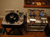
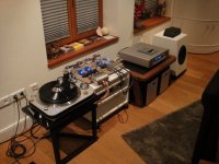
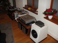
Finally i have some vacation before i go to Vegas. Today we set up my phono system at a friends house. The vinyl trampled the CD in 80% of the cases and that was my most simple stage, the Hiraga Optime Transimpedance stage i have described here. His CD system is not bad at all. An updated Audio Aero directly into the Audionet Max2 Monoblocks. He has a good tonal balance even on the warm side. His speakers are Sonics Allegria S2 with RAAL Ribbon with an active 400W Breeze subwoofer. His room is big and proportioned after Feng Chui. The CD had very good staging and even a measure of microdetail. Were it was better then Vinyl was in bass definition and tightness. Everything else was better then CD. Instruments sounded more typical, treble extention and resolution was better and there was an udeniable sense of presence with the musicians in the room. I show you some photos. From left to right:
The Spiral Groove SG1 with Triplnar arm and Lyra Titan i on my DIY stand. My chaos-fractal cable into the Hiraga Optime into the Transimpecance RIAA. Interconnects are from Wire-World and speaker cables were a double 7m run of Spiral Groove speaker cable.
I have also good news for fellow audiophiles concerning cartridge loading. I talked half an hour today on Skype to Stig Björge of Lyra. Jonathan Carr has gone through the pain of simulating his cartridges plus capacitive loading of cable and Pre. The results will be published in recent setup instructions of Lyra cartridges. Stig will also send the information to me and i will publish it here. As far as i understand it has to do with capacitance and ultrasonic resonance and varies with the cable and stage you use.
Attachments
Scott, interesting how you ashure stability. That could help Rüdiger.
C1/C2 can be bigger, stability was not a big issue with something like AD823. Resistors can be tweaked for very good low gain performance on noise so relatively good to excellent noise performance is available for G = 10dB to 70dB.
After a lot of head scratching i designed a subsonic filter. The starting point was the ESP filter but i wanted to optimise the time domain, lower the amount of caps to the minimum and do it aproximatly complimenting my arm-cartridge combination. My low frequency resonance is at around 10 Hz with a 8dB overshot so i put the -8dB there. I tried to optimise groupdelay as much as possible and ended up with a modified 6th order Linkwitz response. I do this with 2 op amps and 4 caps only. I think this could be useful to get more SPL without cone bottoming and as i learned from the ESP website it could be useful for digital transfer to optimise dynamic range of the A-D converter.