YW - and I investigated for my own good as I am using them (got several types relatively cheap on Ebay). Having said that the difference is pretty small (35mm diameter 10 vs 12 nH, 50 mm 15 vs 16 nH) so I would use whatever I can get. Even small snap-in types are 20 to 25 nH, that is more of a difference though some will claim that it is completely exaggerated to look at such details.
The schematic in my last post contained an error.
T8 was upside down. Thank you AG for alerting me on this mistake.
today i post the corrected schematic with two additions :
one is the possibility to design the current mirrors in the input stage as Wilson types and second, one could shorten the bases of the input transistors ac wise to ground with big capacitors (say 2200 üF) reducing the noise by 3dB.
I did not try the Wilson current mirrors but i know from experience that the capacitors give an improvement in noise suppression.
Next time i will publish some measurements of this circuit compared to some others.
again the schematic does not show the actual values but shows the topology in principle.
On the positive rail by your schematic I read "V15" and on the negative rail "V25". Are there +15V/-25V supply voltage?
Thank you martin for good advice. maybe then i take the stud mounted because thats a little easier to asemble. you can find the data i researched in the rs components catlog but i will lookup the data at epcos website too. they say that the 570 will last 10.000hr at 105° and the 550 5.000hr but i do not care any more, i trust you.
I think it is a good thing when distortion is low and i think circuits with extremely high amounts of feedback can be made to sound good.
Hi Joachim,
thanks for noticing my question to you under syn08's HPS 4.0 phono stage thread and pointing me over to your thread here.
A bit off-topic question but I have to grab you here when I saw your reply under the following link:
http://www.diyaudio.com/forums/analogue-source/154394-hps-4-0-phono-stage-11.html#post1981891
and in particular the part I'm quoting here above whereby a question raised in my head which I would like to forward over to you.
I am aware your reply was probably in the context of phono amplifier, but anyway here below goes my question.
As you have a profound knowledge of loudspeaker designing (Audiophysics) I would like to ask what is your view of amplifiers with high amount of feedback in conjunction with loudspeakers in terms of the overall system distortion?
The reason I ask is as we know, in general high feedback amounts into also very low output impedance of the amplifier and as such I am in particular keen on your view when such amplifier is connected with a loudspeaker.
btw, I remember very well your interview performed by Lars Mytting 1996 and I want to tell I appreciate a lot of your views concerning loudspeaker designing, thanks for your time.
Cheers Michael
Last edited:
that one from post #28 #29 #40 #2 and #3from post #127: what schematic do you refer too? i put quite a lot on this site. values you see on the schemetics are only default and do not represent the correct values. i am still optimising the MPP and when it`s ready and works for my satisfaction i will deliver the correct values.
by the pos. supply voltage rail I read V15 and by neg. rail V25.
Therefore my question about the value of supply voltage
hi michael !
my two reference amps are the MACE Amp and the Audionet Max 2, both with extremely high amounts of feedback. They work with nested feedback loops so unfortunately your question is hard to answer. Amps with high overal feedback can have trouble to damp the back EMF from the speaker in the first 10msec. See research done by Hannes Mayer and Peter Schüller of Stereoplay magazine. They are awaillable by e-mail or you can call them up. I have a third set of amps with tubes (LA Audio monoblocks). They sound very nice on my high sensitivity speaker. I build myself a pair of dipoles with SEAS Exotic driver just for fun. On speakers like that amps with low damping factor can be an advantage because bass and treble will be somewhat higher in level, partly compensating for the reduced bandwidth of those drivers. With speakers of such high sensitivity (96dB in that case plus 6dB difusefield from the dipol) the tubeamp can comfortably stay in class a for best performance. Amplifiers with high output impedance are interesting too because dynamic variation of the driver impedance dos not provoke distortion. I whould do that in an active sytem with equalisation. Nelson Pass can show you how it can be done. The Audio Physic Rhea and Terra subwoofers did something similiar. We used a compromise between constant current and constant voltage because we could not get the amp thermally stable with only constant current. Martin Colloms called the sound of that woofers "athmospheric". If i whould do a poweramp i whould eventually seperate the voltage amplifying stage and the current amplifying stage and add some sort of error feedback. I think Malkolm Hawsford called that kind od design "Pontoon" amps.
To tiefbassuebertr : i use +- 15V for the opamp section and +-12V for the input section
trickled down from the +-15V supply.
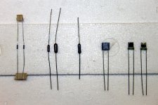
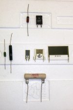
The first picture on the left from top shows resistors for low level work:
from left: 1:small metalfilm from cechoslovakia (maybe Vishay), i buy them in the hundreds and they are dirt cheep and sound good. i use them for prototyps until the dust has setled. 1%, magnetic
2,3: Dale RS55,RS60, 0.1% , low TQ. make shure you get the nonmagnetic. The smaler one is my standart resistor. this is an absolute classic and still not beaten in the medium priceclass.
4: japaneese Tantalum resistor. nonmagnetic. hard to source. i use it sometimes for cartridge loading if i want a liitle bit warmer presentation
5: Caddock metal foil recommended by Borbely. gives somewhat more clarity and resolution if that is desired. Caddock makes even higher spect resistors with even lower TK and closer toerances but i do not have experience with thoose yet.
6. Charcroft Z-Foil naked with Vishey bulkfoil resistive element. Specs are amasing.
TK:Zero, Tolerance 0.01%, very low inductance and noise. If you need the ultimate in stability or improved CMR in differential stages this one is unique. they are made to spec and cost a wopping 25 pound each. I use them in critical places and can build them into my designs if the customer is prepared to pay a premium.
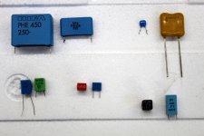
Second picture on the right: capacitors for low level
1. from top left: Rifa PHE450 : i use them for coupling often bypassed with a smaller value when a servo is not posible or not desired. the closest to direct coupling i have heard, very transparent to micro information. does not have the "special" sound of some butique offerings. Also very good for decoupling in power supplies or in speaker crossovers. for crosover work i slighly prefer the Mundorf RFX. They have even less ESR but not by a big margin. I could imagine that teflon caps are even better but i have not tested them in detail yet.
3: top right: blue silver mica from Reichelt Elektronic. I was supprised that the are nonmagnetic and close tolerance. very affordable. i use them for RIAA trimming and miller compensation.
4. top right: Cornell Dublier Silver Mica. Magnetic, availlable in bigger values. They make a lot of different silver micas. I buy this from Farnell. Medium price. They are ultra stable. I use them sometimes in RIAA stages when i want a very dynamic but somewhat bright sound. great for analog filter stages in DA converters where they give a very "fast" sound that fits perfectly well to good digital.
5: low left: Röderstein-Vishey MKP (blue) and Wima FKP : both of them availlable with 1% tolerance. Good for RIAA stages. I usually parallel some to get even closer tolerances and lower loss. Again i did not try Teflon but i plan to do that.
6: Wima MKT (red) they are small and availlable in quite high values. I use them for servo work and as coupling capacitor in more affordable equipment. Epcos MKT: designed for EMV suppression in cars. i use them for cartridge loading, decoupling and of cause to suppress HF. I know they are not of fancy PP but i like them nevertheless.
7: LCR extended foil Styroflex. i use them in RIAA stages as an alternative to Röderstein MKP or mix both. Bigger values Röderstein, smaller values LCR. they have 1% tolerance but one in 10 is maybe slightly of so i measure them before i insert them. i have heard strange things about their sound on the web but found it is ********. they are very good.
from left: 1:small metalfilm from cechoslovakia (maybe Vishay), i buy them in the hundreds and they are dirt cheep and sound good. i use them for prototyps until the dust has setled. 1%, magnetic
2,3: Dale RS55,RS60, 0.1% , low TQ. make shure you get the nonmagnetic. The smaler one is my standart resistor. this is an absolute classic and still not beaten in the medium priceclass.
4: japaneese Tantalum resistor. nonmagnetic. hard to source. i use it sometimes for cartridge loading if i want a liitle bit warmer presentation
5: Caddock metal foil recommended by Borbely. gives somewhat more clarity and resolution if that is desired. Caddock makes even higher spect resistors with even lower TK and closer toerances but i do not have experience with thoose yet.
6. Charcroft Z-Foil naked with Vishey bulkfoil resistive element. Specs are amasing.
TK:Zero, Tolerance 0.01%, very low inductance and noise. If you need the ultimate in stability or improved CMR in differential stages this one is unique. they are made to spec and cost a wopping 25 pound each. I use them in critical places and can build them into my designs if the customer is prepared to pay a premium.
Second picture on the right: capacitors for low level
1. from top left: Rifa PHE450 : i use them for coupling often bypassed with a smaller value when a servo is not posible or not desired. the closest to direct coupling i have heard, very transparent to micro information. does not have the "special" sound of some butique offerings. Also very good for decoupling in power supplies or in speaker crossovers. for crosover work i slighly prefer the Mundorf RFX. They have even less ESR but not by a big margin. I could imagine that teflon caps are even better but i have not tested them in detail yet.
3: top right: blue silver mica from Reichelt Elektronic. I was supprised that the are nonmagnetic and close tolerance. very affordable. i use them for RIAA trimming and miller compensation.
4. top right: Cornell Dublier Silver Mica. Magnetic, availlable in bigger values. They make a lot of different silver micas. I buy this from Farnell. Medium price. They are ultra stable. I use them sometimes in RIAA stages when i want a very dynamic but somewhat bright sound. great for analog filter stages in DA converters where they give a very "fast" sound that fits perfectly well to good digital.
5: low left: Röderstein-Vishey MKP (blue) and Wima FKP : both of them availlable with 1% tolerance. Good for RIAA stages. I usually parallel some to get even closer tolerances and lower loss. Again i did not try Teflon but i plan to do that.
6: Wima MKT (red) they are small and availlable in quite high values. I use them for servo work and as coupling capacitor in more affordable equipment. Epcos MKT: designed for EMV suppression in cars. i use them for cartridge loading, decoupling and of cause to suppress HF. I know they are not of fancy PP but i like them nevertheless.
7: LCR extended foil Styroflex. i use them in RIAA stages as an alternative to Röderstein MKP or mix both. Bigger values Röderstein, smaller values LCR. they have 1% tolerance but one in 10 is maybe slightly of so i measure them before i insert them. i have heard strange things about their sound on the web but found it is ********. they are very good.
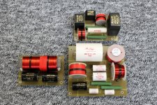
post 132, components for speakers, first row top:
1: left: Drahloric Wirewound, i used them in clasic Audio Physic speakers like the Avanti1 for tweeter padding.
2: right: Isabellenhütte Isaplan, i used them in Audio Physic top models like the Kronos
second row:
1: Sfernice Wirewound. my favourite for soft dome tweeters
2: Welvin Wirewound. an alternative
3: BI components thick film resistors in various power ranges, TT and Ohmite make similiar types. Vishey make thick film too but they are in a plastic case with terminal lugs. sound is neutral, some may say analytic
third row:
Mundorf Supreme nonmagnetic wirewound. the best combination of resolution and musicality in my experience. not inexpensive though.
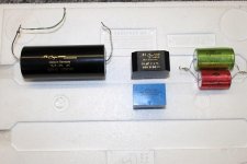
Second picture:
1. Mundorf Supreme. I use Silver-Oil and Silver-Gold-Oil. Can not sell to Japan without them
2. Mundorf RXF and Audyn MKP. RXF is my favourite. RXF combined with Audyn is an alternative
3. WEGO flat foil eectrolytic. they make bipoar electrolylics longer then i can think. surprisingly close tolerance (5%) and extremely reliable. some speakers i build with them 30 years ago still work today. i use them in resonance circuits where i need big values. they produce caps for other brads too. they are all the same.
right picture: Mundorf crossover for current Sonics speakers. I am very happy with the new woofer coil they made me (pictured on the left). they are bobbinless wound directly on a bar of transformer sheet metal. very compact, low distortion, low ohmic loss.
1: left: Drahloric Wirewound, i used them in clasic Audio Physic speakers like the Avanti1 for tweeter padding.
2: right: Isabellenhütte Isaplan, i used them in Audio Physic top models like the Kronos
second row:
1: Sfernice Wirewound. my favourite for soft dome tweeters
2: Welvin Wirewound. an alternative
3: BI components thick film resistors in various power ranges, TT and Ohmite make similiar types. Vishey make thick film too but they are in a plastic case with terminal lugs. sound is neutral, some may say analytic
third row:
Mundorf Supreme nonmagnetic wirewound. the best combination of resolution and musicality in my experience. not inexpensive though.
Second picture:
1. Mundorf Supreme. I use Silver-Oil and Silver-Gold-Oil. Can not sell to Japan without them
2. Mundorf RXF and Audyn MKP. RXF is my favourite. RXF combined with Audyn is an alternative
3. WEGO flat foil eectrolytic. they make bipoar electrolylics longer then i can think. surprisingly close tolerance (5%) and extremely reliable. some speakers i build with them 30 years ago still work today. i use them in resonance circuits where i need big values. they produce caps for other brads too. they are all the same.
right picture: Mundorf crossover for current Sonics speakers. I am very happy with the new woofer coil they made me (pictured on the left). they are bobbinless wound directly on a bar of transformer sheet metal. very compact, low distortion, low ohmic loss.
Hi Joachim,
thanks for your reply!
The research by Hannes Mayer and Peter Schüller of Stereoplay magazine would be an interesting read, did you mean I could send them an e-mail, actually I had quick look at Stereoplays homepage and unfortunately my German skills aren't the best but if the paper is in PDF or other text file format I could of course use Google translate, do you happen to have any of these guys e-mail you could perhaps send me a PM?
Agree with you there are many interesting technics to try out, also I have been thinking of an equalized amplifier design for a loudspeaker design I had in my mind and I had some ideas also to tailor each amplifier to have its own sonic signature for the the woofer, middle and tweeter amplifier all of them little bit differently designed for their particular task. Your idea about separating the voltage gain stage and current gain stage in the amplifier is something I also have been thinking of, two shorter "half-global" feedback system (if we may call them like that) instead of one GFB spanning over the whole amplifier, if I recall my memory correct to my mind comes also the Halcro design which used OP-AMP around each MOSFET at the output stage in an way to to make the output stage very linear which reduced the load from GFB a lot. Well there are many interesting ideas and just limited by ones own imagination.")
Cheers Michael
thanks for your reply!
The research by Hannes Mayer and Peter Schüller of Stereoplay magazine would be an interesting read, did you mean I could send them an e-mail, actually I had quick look at Stereoplays homepage and unfortunately my German skills aren't the best but if the paper is in PDF or other text file format I could of course use Google translate, do you happen to have any of these guys e-mail you could perhaps send me a PM?
Agree with you there are many interesting technics to try out, also I have been thinking of an equalized amplifier design for a loudspeaker design I had in my mind and I had some ideas also to tailor each amplifier to have its own sonic signature for the the woofer, middle and tweeter amplifier all of them little bit differently designed for their particular task. Your idea about separating the voltage gain stage and current gain stage in the amplifier is something I also have been thinking of, two shorter "half-global" feedback system (if we may call them like that) instead of one GFB spanning over the whole amplifier, if I recall my memory correct to my mind comes also the Halcro design which used OP-AMP around each MOSFET at the output stage in an way to to make the output stage very linear which reduced the load from GFB a lot. Well there are many interesting ideas and just limited by ones own imagination.
Cheers Michael
send me a privat message and i will put forward your request to hannes.
we did things like you mentioned in the 80th. i worked with Omtec at that time and Manfred Bayer the designer could change the sound of his amps by setting the open loop bandwidth to certain different values so he could optimise for bass, midrange and treble.
you know, high damping factor in the bass and less feedback in the treble or the other way around, i can not remember. we tried even a negative output impedance. good luck with that aproach. optimising active sytems can be tricky and extremely time consuming. there are simply incredibly lot`s of options. concerning seperating the input stage and output stage, the fist that did that to my knowlege (with transistors, that is) was Nelson Pass with his Stasis amps. Cerainly they where the first transistor amps i heard (not counting class a devices like the Levinson) that had not the typical spitty treble and a very deep soundstage to behold. I think he reversed the output transistors to have voltage gain and used a lokal feedback loop. he also paralleled a lot of devices to restore some damping.
Today i got an awful lot of things done and i am happy to tell you that i succeeded big time. i had to disassemble everything and that was no fun. it really gets jammed in there.
First i got the DC offset problem solved. When i first build the circuit i got around 10mV offset from the input stage. the following stages have around x 900 DC gain so the servo was JUST able to capture. it seems that over time the offset got a bit worse so the servo could not track the DC any more. It is not "mighty" enough as we say here. So i changed R11 and R12 to a higher value to lower DC gain. That has also the advantage that distortion from this stage will be 3 times less and bandwidth will be 3 times higher. I would not make those resistors any bigger because the circuit will get noisier. to compensate the loss of AC gain i added an output stage. I just had developed an input stage for my new preamp so that circuit came in handy because it was already build and had the right properties. This has the benefit that the overload margin got up.
with +-12V supply the MPP can now deliver +-8V RMS without distortion. In the treble it is rather better because i do the 75 usec EQ in the first stage. So no trouble John with miss tracking cartridges. The output stage adds virtually no distortion and is not so stupid as it seems on first sight. I use a precision transimpedance amp with good current delivery (100mA) and great speed (50MHz-3dB). input impedance is set to lower DC gain and reduce common mode distortion. I bias the output into class a with a 7mA constant current source to the minus supply. the next stage of my preamp has quite a low input impedance of 4.2 kOhm so that makes shure that the output stage of the MPP stays in class A all the time. One advantage of the new arrangement is that i can drive long cables very well now. my turntable is 4m from the system so for me that is a good thing. i also found that an added buffer can improve the sound in terms of dynamics and
slam in the bass. If you lower the output resistor to say 10 Ohm and ad a potmeter it also makes a great Headphone output. So here we have the new gain structure i am happy with (all at 1kHz). First stage 24dB, second stage 10dB, third stage 20dB, output
stage 10dB for a total of 64dB with a 5 Ohm cartridge. Idle current in the input stage is 3.5mA per transistor, the folded cascods are running on 2mA, a compromise for optimum noise on a 220 Ohm resistor and class A drive on the 680 Ohm resistor. I give two circuit diagrams that now have also most of the correct values and types. the first is what runs in my lab because i have the outpiut stage in a seperate box. 1: the Servo is not tracking the output, that is no big tragedy because of impedance matching in the output stage. Is has a maximum of 10mV but hovers aroud 3mV most of the time. 2: servo wrapped around the output. should give around 1mV with the AD711 i use. this is not an optimum choice i just had them lying around. the OPA134 or OPA132 is better and for the freaks there are other op amps that are even better specked DC wise. i doubt that they sound any better though.
Attachments
Next i show some measurements.
from left : 1:distortion with and without output stage at the same level over frequency
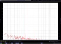
2: spectrum of 1kHz tone with and without output stage
3: overload margin at 1kHz
from left : 1:distortion with and without output stage at the same level over frequency
2: spectrum of 1kHz tone with and without output stage
3: overload margin at 1kHz
Attachments
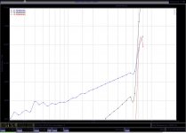
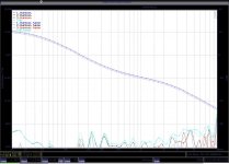
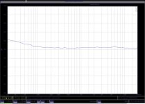
this files show the gain (+64dB) anf the RIAA curve. I had worked on it a little and put 320kOhm resistors in instead of 330kOhm. There is still a 33kOhm in the circuit that should theoretically have 31.8kOhm so at 20 Hz there is a gain of 0.8dB. i keep it that way for listening on the wekend. i like powerfull bass and have an adjustable subwoofer.
basically the result shows that mathematics are correct.
basically the result shows that mathematics are correct.
Attachments
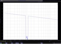
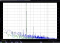
You will not beleave it but i found the time to make some TIM measurements on head amps (or pre-pres)
I find a lot of concern here on the web about TIM problems in circuits with Negative Feedback so first i measured an open loop circuit. It is the AKSA Paris. A single ended fet-bipolar cascode design with no source degeneration. The amplitude is -40dB/U (10mV RMS) as a compromise between low level resolution and dynamic range.
From left to right:
1: TIM measured with noise methode. A pink noise signal is fed into the stage and part of the spectrum is suppressed. the residuum is shown and should ideally be zezzo
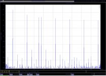
2: TIM measured with the squarewave method. a sinewave mixed with a squarewave is presented to the stage. intermodulation products are shown
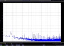
3: the infamous Belcher test. a multi spectrum of tones spread around the audible range is put into the amp. tones are choosen in frequency to not intermodulate with one another. tones are then digitally suppressd and the residuum in shown. this test is known for good correlation with subjective soundquality e.g. the better the spurious signals are suppressed, the more "transparent" the amp is
I find a lot of concern here on the web about TIM problems in circuits with Negative Feedback so first i measured an open loop circuit. It is the AKSA Paris. A single ended fet-bipolar cascode design with no source degeneration. The amplitude is -40dB/U (10mV RMS) as a compromise between low level resolution and dynamic range.
From left to right:
1: TIM measured with noise methode. A pink noise signal is fed into the stage and part of the spectrum is suppressed. the residuum is shown and should ideally be zezzo
2: TIM measured with the squarewave method. a sinewave mixed with a squarewave is presented to the stage. intermodulation products are shown
3: the infamous Belcher test. a multi spectrum of tones spread around the audible range is put into the amp. tones are choosen in frequency to not intermodulate with one another. tones are then digitally suppressd and the residuum in shown. this test is known for good correlation with subjective soundquality e.g. the better the spurious signals are suppressed, the more "transparent" the amp is