Velvetsunrise, maybe you missed some parts of the thread but your circuit shows my Transconductance-Transimpedance (TC-TI) stage in simplified form that was discussed here before in detail. You can adjust the gain of that circuit over a very wide range by changing the the impedance of the RIAA network. I found circuits with gain from 56 - 66dB worked well. In this circuit everything is intermingled with everything. For example raising gain also raises distortion and lowers overload margin.
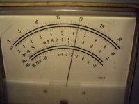
I have now the Olypos in my system with a TC-TI stage. I was curious how it compares to the Titan i so i did make some measurements. First i measured crosstalk with a 1kHz tone at 5cm-sec on my DIN testrecord. The Olypos with -40dB does a little bit better then the Titan i but the 3dB difference can be due to measurement tolerance.
Attachments
Then i measured frequency response with pink noise and anti pink filter. The Olympos does not suffer the slight 10kHz peak of the Titan i but has some more treble over 15kHz so this may acount to the notion that the Olympos sounds softer and more musical then the Titan i for some listeners that prefer clasical. I found the subjective difference rather small but i can understand why the Olympos is still considered the best Lyra cart of all time.
Attachments
Here is the noise of the TC-TI in its latest disguise. The right channel is somewhat better and when i crank the system i can here some more noise in the left channel that sounds impusive like crackers. At standart volume ( i listen loud ) this is a non issue still i think some noise screening could help and i am thinking about a reliable method for some time. Manuel Huber of FM Acoustic told me that they do it with electrostatic hedaphones by putting the transistors in a jig but when you see my maesurements the differeces show up. Especialy in the bass.
Attachments
Two things stand out. One is that the Olypos has around 3dB less distortion then the Titan i but again i do not trsust my measurements 100%. Maybe i have adjusted it better, maybe the needle was cleaner, maybe my room temperature was more comfortable, who knows. What you can really see is that making a phonostage with distortion less then
- 60dB may not help to make it sound any better. Distortion at that level ( 5cm-sec) is -46dB in the Olympos, all harmonics are present, exponentially falling. That distortion profile sounds jsut fine to my ears and the -90dB second of the TC-TI and the -110dB of nothing particular in the FPS are more then good enough. Again see the dynamic range of the vinyl record at around 72dB, just as burkhard Vogel sugested. Still you can hear a 1kHz sinewave at -30dB burried in the noise so subjective dynamic range of Vinyl can be very good. A friend of mine with superb listening found Harry Bellafonte at Carnegie Hall distorted in comparison to his lates Linn server with 24Bit-196K though. I am much more tolerant and find the Belafonte amasing in terms of involvement although i hear the technical problems too. It is like looking at an old black and white photograph so enjoying vinyl is also an eastetic experience that does not always tell the truth.
the other interesting thing is that i got rid of the 50Hz hum. I use the Hypnotise PSU and could not help to put at least one Elna Silmic2 330uF into the plus and minus feed but i think even that is not necesary with a Hypo board so me that has always decoupled generously have to rethink. all fine though. Saves me money and trouble.
I have not being posting for a while because i was on a trip to Berlin and then to Hamburg. I had enough time in the train to think about what i should do next and one thing i really need is a passive Anti RIAA. I have build the Vogel active Anti RIAA but it is not always practical. For example i am planning to feed a high quality Digital Signal from my SACD player into some of my circuits to make a straight wire bypass test. Also i have to check RIAA accuracy of my latest TC-TI designs. Sofar they have been first simulated and then build but because i use current mirrors with finite output impedance a small mistake in the deeper regions under 100Hz can develop that comes out a bit different in reality although we simulate the impedance too. Current mirrors with very high, even infinite output impedance ( or negative ) can be build but a current mirror also has a transient response based on the topology. That all happens over 10MHz but still i found they all sound a bit different. Interestingly the simple Widlar mirror is the fastest without overshot. The Wilson is as fast but with a slight overshot.The Cascode mirror is only 1/3 of the speed of the Widlar but does not have an overshot and the 3 transistor mirror is even slower with the biggest overshot. So in praxis the mirror with the highest ouput impedance may not be the best choice for sound. If the mirror does not have an infinite output impedance the RIAA at lower frequencies will load the mirrror with say 100kOhm and when the mirror has 1Mohm at that frequency for example you have a loss of bass. That may not be much, say 1dB but it is not perfect so the RIAA has to be tweaked. A qiuck check with a passive RIAA can help and feeding for example a 100kHz squarewave shows how the RIAA hehaves concerning pahse and transient response. Even the clever Vogel circuit runs out of steam somewhere over 300kHz because gain in that circuit is not infinite at higher frequencies but the RIAA demands an even falling response to zero.
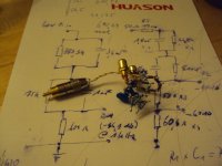
investigating the material i found on the net there is a good article on the Hagerman website. It starts with the legacy Lipshitz circuit and makes some additions and modifications. What still worries me is that the load impedance is not specified and with the exeptions that Hagerman specifies a 50 Ohm input impedance ( Lipshitz just labels "Low Z In") and remodels the Anti RIAA to give out signal at -40dB and -60dB ( the Lipshits specifies a somewhat curious -44.1dB ) i see no real innovation. The Neumann pole can be added to the Lipshits too so this is not exclusive for the Hagerman solution. It ocurred to me that a load impedance has to be specified and i decided on 300 Ohm. At least with my recent circuits that gave a very good subjective result with the cartridges my friends and i are using e.g. Low Output - Low Impedance types like the Lyras. Higher loading like 1kOhm and 47kOhm did not give any more information and the sound got sharp at times. Tubes or other circuits may behave different but at Maison Gerhard 300 Ohm is the norm. I decided to work on the Lipshitz, partly because i had the values at hand and partly because i never use the Neumann constant. I substituted the 604 Ohm resistor in the Lipschitz with 5x 113 Ohm Dale in series and 2 x 113 Ohm in parallel. With 300 Ohm loading this amounts to 612,61 Ohm.
1% off whould be 610.04 Ohm so i found that close enough. A load of 118 Ohm whould give 603,2 Ohm what is very close but also shows that loading down is posible without much change so the circuit is not particular sensitive which is a bonus.
Attachments
What I would find most interesting: If you model a riaa-network with spice, those R-C nets introduce a lot of distortion, and one has to undertake some measures to get it cleaner. However, it is often magnitudes worse than the same circuit without riaa network. How does a real life RC-RIAA behave distortionwise?
Rüdiger
Rüdiger
The trick is that no voltage develops over the RIAA and that can be done in a Transimpedance circuit. To compare a RIAA circuit with a linear circuit is not directly posible. As a worst case szenario you could make that resistor 100kOhm what is aproximately the impedance of the RIAA at low frequencies and then the linear circuit does not look so well any more.
Joachim, maybe you should really look into LT Spice, which you can download for free from the Linear Technology Website.I.......one thing i really need is a passive Anti RIAA. ......
1. You can feed a circuit as attached (which performs a inverted RIAA with Laplace transform) with white noise or whatever test signal you need in .wav format (you can create it with eg. audacity).
2. Let LT spice perform the simulation.
3. Afterwards, LT spice can write the output .wav to a file, and you can burn it to a CD.
4. Feed your phono stage with the cd signal = inverse RIAA, appropriately attenuated. Et voilà.
Ciao, Tino
-
Attachments
What a funny way to do it. I do he same with LSP-CAD when i design speakers. We simulate with Microcap but still when you put the circuit on a PCB or my Air Sculpture Style if you wish the output is a bit different in praxis.
For example in Microcap one of my TC-TI stages had the RIAA curve maintained up to 10MHz. When i measured it the -3dB point was at 400kHz.
For example in Microcap one of my TC-TI stages had the RIAA curve maintained up to 10MHz. When i measured it the -3dB point was at 400kHz.
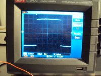
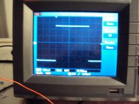
I made some measurements with my new passive anti RIAA on one of my TC-TI stages with cascoded current mirror.
First is a squarewave at 1kHz, then 100Hz, then 100kHz.
First is a squarewave at 1kHz, then 100Hz, then 100kHz.
Attachments
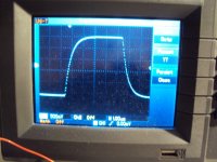
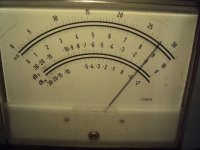
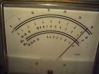
RIAA is better then +- 0.2dB from 100Hz to 20Khz and there is a slight 1dB bump at 20Hz i expected from the simulation and designed in for a friend that needs a full sound at low volume. I am very happy with that result. My anti RIAA should be accurate +-0.1dB from 20Hz to 20Khz and the reast can be explained by +-1% tolerance of the components.
The -3dB point is at 400kHz whereas simulation sugests a flat response up the 10MHz. This TC-TI stages are damned fast and this result sugests the limit of accuracy of the anti RIAA.
The -3dB point is at 400kHz whereas simulation sugests a flat response up the 10MHz. This TC-TI stages are damned fast and this result sugests the limit of accuracy of the anti RIAA.