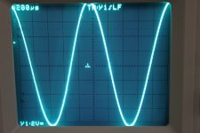
I measured overload in the MPP again, this time compensating for the RIAA curve.
I could not get a consistent reading at 20Hz due to the sampling rate i am using so i did the bass overload at 100 Hz. I do not think that distortion at 20Hz whould be any higher.
I also tested the overload on the scope and got 17V P-P "without visible waveform distortion" as my old professor whould say. this is rather more then my calculatet 14.1 V. the reason is that i defined overload as 0.1 % distortion. the improved version of the MPP will swing to 31 V P-P when i drive the output stage on +-18V supplys ( the maximum alowed with the OP Amp choosen - 5V because it can not drive rail to rail). i rather whould not recommend that because i found that many OP Amps sound better on a lower supply like +-12V to +-15V. Thermal problems may come into play here. Try it out, i whould not like to start a discussion abbout that here.
Attachments
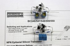
I have build an unbalanced version of the MPP in the meantime. I used 2SB737 and 2SD786 selected for Hfe and VBE this time. As expected distortion is much lower and gain is higher due to the much better Hfe matching. After this experience i can not recomment the MAT02/03 combination any more. The Hfe matching is poor because the PNP type has much lower gain. Instead of the hard to source ROHM transistors other types could be used, for example the ones that Syn08 recommends. You could also make your own cheap low noise transistors from a row of 4 BC550C and BC560C or even better from 4 2N4401 and 2N4403. The unbalanced version has a noise advantage of 3dB compared to the balanced MPP. i have reduced the circuit to the absolut minimum so it is a good project for DIY. i build only the head amp because i have a lot of MM stages around. i needed around 6 hours to make it with the help of one employee who made the mechanical things so it could be done on one weekend. i will give the full diagramm with all values later. Now i go home for a listen.
P.S.: i did some other changes for improved performance. first i thermocoupled the inputstage (see picture). bias is now quite stable and with some trimmimg of the constant current source DC coupling is posible. i used a good quality coupling cap here. i changed the constant current source for the foldet cascode. on the first prototype i used a half LSK 389 near IDSS, not a very high impedance source. i changed to a BF246A set to 9mA. i found that stable bias is very importand in open loop circuits and having compared the fet to a simple resistor i watched a major improvement in distortion when the fet was in action. this 9mA rases the idle current in the foldet cascode stage and it runs now on 13mA able to swing more then 4V Class A into the 340 Ohm transimpedance resistor. This idle current is a liitle high for optimum noise match to the 220 Ohm resistors but the total noise is still around -140dB.
P.S.: i did some other changes for improved performance. first i thermocoupled the inputstage (see picture). bias is now quite stable and with some trimmimg of the constant current source DC coupling is posible. i used a good quality coupling cap here. i changed the constant current source for the foldet cascode. on the first prototype i used a half LSK 389 near IDSS, not a very high impedance source. i changed to a BF246A set to 9mA. i found that stable bias is very importand in open loop circuits and having compared the fet to a simple resistor i watched a major improvement in distortion when the fet was in action. this 9mA rases the idle current in the foldet cascode stage and it runs now on 13mA able to swing more then 4V Class A into the 340 Ohm transimpedance resistor. This idle current is a liitle high for optimum noise match to the 220 Ohm resistors but the total noise is still around -140dB.
Attachments
Syn08, is that a HP3563?
Joachim, please consider the overall picture, when it comes to phono overload. We have measured this over the decades, and truly it is often too little in many designs, BUT where does this extra output go, once it is generated? Yes, in the input attenuator. If you have significant overload problems, then you usually have too much forward gain. This can be reduced, often improving distortion performance.
Joachim, please consider the overall picture, when it comes to phono overload. We have measured this over the decades, and truly it is often too little in many designs, BUT where does this extra output go, once it is generated? Yes, in the input attenuator. If you have significant overload problems, then you usually have too much forward gain. This can be reduced, often improving distortion performance.
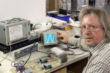
Overload is simply not a problem in the MPP because i do the 75usec RIAA right in the first stage as part of the transimpedance gain structure, so gain at higher frequencies goes infinitesimal to zero, lowering distortion the higher the frequency is. Bass overload could be a problem with warped records but i use a rubber ring to lift the record and then press it down with a clamp. on the other hand my records (most) are in mint shape, i simply took good care buying and handling them. this little picture shows only my small analog lab where i check for very basic things. i have three other labs with laser scanners, accelerometers, extremely expensive microphones and a complete measurement suite for electronics measurements at infinitum. i have access to the latest Audio Precision and Rhode & Schwartz gear but does that make a better product ? Anyway i am very impressed Syn08 and you speak german too !!!! that´s not an easy language.
and you speak german too !!!! that´s not an easy language.
Ich habe sieben Jahre Deutch gelernt, als ich ein Kind war.
Here is the circuit diagram of the DIY version of the MPP unbalanced head amp.
I will listen to it on the weekend and you will be very surprised how good the measurements look with this really simple topology. I can not hear any noise at the listening seat even at quite high volume and i live in a very quiet rural place. i will ask my son who has frequency extention to 20kHz ( i check that from time to time) if there is something unpleasant.
I will listen to it on the weekend and you will be very surprised how good the measurements look with this really simple topology. I can not hear any noise at the listening seat even at quite high volume and i live in a very quiet rural place. i will ask my son who has frequency extention to 20kHz ( i check that from time to time) if there is something unpleasant.
Attachments
No, only Syn08 speaks German. I know a little French, that's all. I have visited, Munich, Hamburg, and Berlin over the decades, even went to E. Berlin, once, and nearly got myself shot. ;-)
Really good test equipment is nice, but not for this task. I just turned down the use of an Audio Precision for a new phono project, for example. Stick with open loop if you can.
I too do the 75us time constant in the first stage as part of the transconductance out gain structure. Works for me. Where is your arm resonance?
i just come back from a meeting with donald fagen, louis armstrong, duke ellington and matia basar end forgot to tell you that i use a mono subwoofer that sums the channels under 70 Hz. my midrange drivers have quite a stiff suspension, that helps to suppress high extension too.
and you build without serious listening.
That is incorrect. I only don't trust my ears enough, to talk about the results.
OT posts moved here:
http://www.diyaudio.com/forums/lounge/155446-some-serious-workspace.html
http://www.diyaudio.com/forums/lounge/155446-some-serious-workspace.html
Here is the circuit diagram of the DIY version of the MPP unbalanced head amp.
I will listen to it on the weekend and you will be very surprised how good the measurements look with this really simple topology. I can not hear any noise at the listening seat even at quite high volume and i live in a very quiet rural place. i will ask my son who has frequency extention to 20kHz ( i check that from time to time) if there is something unpleasant.
Aha! An AD844 in disguise.... Except maybe for the noise?
jd
i will try to measure it. i have software from dr.feikert that can do that. anyway did mark levinson not say a long time ago "i am not interested in theory, i am intested in results".
anyway, i asume 4 to 6dB. allen perkins and i found that too much damping destroys other aspects of the sound like immediacy and a certain feeling of freshness and "jump" factor.
a good example of a high amount of damping is the original firebough turntable. it never cut the mustard for me in terms of dynamics and feeling of being in the presence of the musicians. it sounded tired and slow for me. comparing the sound of equipment to the life sound experience is alien to many here i found. it is simply not enough for good sounding equipment to copy and amplify the input signal because that signal is already flawed. one example: a friend and me designed an amplifier for Dr.Forsell. the good doctor likes to fumble so we gave him four potmeters he could adjust: bias current, dc offset, feedforward and feedback. jonathan scull wrote in stereophile that this was the best amp he ever heard. john atkinson in the lab was toally shocked to find enormous amounts of traditional crossover distortion. anyway, human perception is not a simple maschine with input and output. if it where that way then take any aplication from analog devices, nat semi or burr-brown, shut your mouth and make tons of money. you know that john, it´s not that easy.