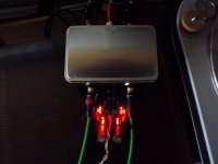
This is how the tidyed up setup looks now.
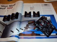
I know that box!
")
jd
could a Hypnotize beeing made with +-17V ? The circuit i whould like to supply whould draw 160mA so a bit more then the 100mA that the stage on the last picture needs.
Yes but it takes modifications and sinks. Here is how.
Remember, when you add resistor to extend Vout as in the guide, you lose the benefit of bypassing the Vref with just mini MKP. You will need theVref bypass lytics back, else the closed loop gain is going to suffer in the lows. Full LEDs for 10V can do it with only MKP, resistor is a passive Norton ref. But you still can use one 1837 under each lytic for some help.
Did you have any better experiences with the additions of Nichicons, 1837s, 160mA CCS, shorter cables? Listened more?
Did you have any better experiences with the additions of Nichicons, 1837s, 160mA CCS, shorter cables? Listened more?
Yes, i listened more. I kept the circuit under current all the time. As i already said, noise dropped and bass got more robust. I have no objections any more in the treble so this is a full success. I also finished my buffer. When you see the diagram, you maybe disappointed. It is very similiar to PMAs and has only best praxis and some little tricks that inprove the sound in my opinion. It does what i want though.
Posting will be in 10 minuts and i will include a picture of the build.
Posting will be in 10 minuts and i will include a picture of the build.
Here is my buffer. It is the well known combination of OPA134 and BUF634. The OPA134 is something like the new NE5534, not because it is technically in any way similiar but because you see it everywhere even in very expensive equipment. The reason is not totally clear but it is affordable and availlble, has low offset and noise plus low distortion if you use it wise. Most people seem also to like the sound more. Technically is has some disadvantages over the NE, namely it does not like to be driven into a load of under 2kHz and it has some more common mode distortions both well documented in D.Selfs books and S.Groners survey of Opamps so i do not repete the resond why here. Both affect treble distortion and that may make the sound so attractive or say different to the more matter of fact sound of the NE. I tryed to avoid both pitfalls in my little project and here is what i did. First i connect the ouput to a high impedance node, in this case the BUF634. It is a well matured part and has the advantage over the new National LME buffer that it has a tendency to have the same output offset then the driving opamp. The LME has lower open loop impedance and sounds more dynamic but it is not easy to avoid oszillation and it needed a servo in all circuits i tryed. Both is a no-no for my aplication. I can not use a servo out of reasons that go beyond this thread and i can absolutely not afford oszilation. That is also the reason i use the 220pf compensation cap. Sometimes you see a 100 Ohm resistor betwen Opamp and buffer, i left that out here. To avoid common mode distortion a compensation resistor can be inserted that has idealy the same value as the driving impedance. I decouple with 10uF close to the BUF and 01uF from plus to minus supply. I do this most of the time and got critisied badly for that here. The consensous is that all caps shoud go to ground but in praxis it works superbly well and i seldom run into stability problems even with fast circuitry. Now comes my little twist that i found after carefuly studying the OPA134 specsheet. I bias the OPA134 in class a with a 5.5Kohm resistor from ouput to one off the supplies. This can be done more sofisticated and you can see a variety of ever complicated options on the Tangentsoft webpage. Soundwise i dd not hear a huge difference of the various biasing strategies so i go with the single resistor here. It has the advantage that it does not add any capacitance that coud upset the buffer. Usually it is recommended that the resistor is tyed to the negative supply. That comes from the time where the IC manuactures where not able to process a complimentary NPN-PNP pair and by switching of the PNPs or the rather complicated workaround in the NE, the more linear NPNs do the job alone in class a. It is argued that this reduces distortion but for a closed loop design like this i could actually not measure any improvement down to -130dB, my measurenet limit. Somewhere on the web a saw another breef explanation why this could sound better. In many Opamps PSU supression is not the same in the minus conpared to the plus feed. The OPA134 is a particular design in that sense that the positive PSU rejection is some 25dB worse than the negative rejection. I thought why not connect the resistor to the POSITIVE supply and not do what all others do something could happen and voila, it did. Better sound with a smoother and better resolved treble. Now you see that even in a standart and primitive design like this , soul is in the details.
Attachments
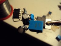
I need very high input impedance and very low output impedance with little offset. The current drive ability is a byproduct and i do not absolutely need it. It can be reconfigured as a headphone amp with feedback resistors. See the BUF634 datasheet. In that case i whould use 10 Ohm at the output. Could drive my AKG too. Configured with a gain of two and a 50 Ohm resistor at the ouput and parallel to the next input very long cables can be driven without transmission loss eg. reflexions. See PMAs site.
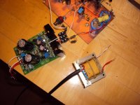
I am building a second Hypnotize to supply another experimental stage. I need 2 x 17V.
I mounted the Fets on bigger finns this time. That makes some mechanical trouble but i can solve that. I will use 6.8 Ohm set resistors this time. I have already mounted the two Leds with the test resistor. I use a 250 Ohm because i did not have a 200 Ohm. I have to go though Salas text ones more to not make any mistake. I start to understand this circuit better but not in full and i am really fascinated that it gave such a good improvement in sound over the LC Audio. I am using a split bobbin frame transformer with 2 x 18V AC.
I have used that transformer for a standart 2 x 24V supply before. See picture.