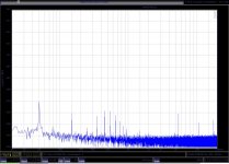
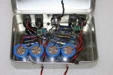
next comes the Quantummusic Goldstandart my best commercial efford. Watch the extremely low noise in the Paris. The Goldstandarts actually sold have 4.5 to 6dB less noise because of massive paralleing. Shown is my lab sample.
The Goldstandart has a copious amount of shunt feedback in the first stage and massive NFB in the second stage so the measurement of a Head-Amp with parallel NFB is missing here but i expect no miracle. Actually it gets a bit boring. I get more and more the impression that conventional distortion measurements are sufficient to discribe the performance if the design is not totally incompetent so draw your own conclusions.
Yes, they all sound different my son tells me that still can hear up to 20kHz in his young age. Why will always remain a mystery. that is where the "Art" part comes in for me.
P.S: sorry , i can not find the squarewave test on the USB stick.
i promiss i send it tomrrow
Attachments
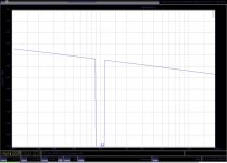
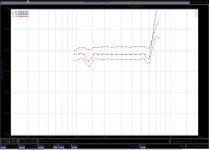
here comes the squarewave TIM measurement of the Goldstandart.
I show the Paris here again for comparison (2nd picture from left)
the picture on the right shows the MPP output stage.
I show the Paris here again for comparison (2nd picture from left)
the picture on the right shows the MPP output stage.
Attachments
So the MPP works now. What to do next ?
If i whould build it the next time i whould certainly thermocouple the input-stage because there is still a little bit to much DC fluctuation. the servo is quite slow so it can be up to 10mV at the ouput at times. Today i tried a DC adjustment on the cascode stage that can minimise DC offset from the input stage but the cartridge has to be connected and the amp warmed up for say 20 minuts to do the adjustment. a servo could be used on the inputstage but i rather would like to avoid that for simplicity sake. and i really whould like to spare me the discussion if a servo could do any harm at that point of the circuit.
also i may not use the MAT02-03 in my next build because i fried an expensive set during experimentation. i also have the SSM parts that are also low noise matched pairs and they are considerable cheeper although some people claim that they do not behave the same (they are not so easy to source any more but with some patience you can get them). If you are prepared to pay a premium take the MAT02/03 for piece of mind. they are excellent and have prooven to work well in this topology. there is a THAT chip that has 2xPNP and 2xNPN on one chip and could be interesting too. i also have a big collection of low noise bipolars from ROHM and Toshiba so i should have some luck to find well matched octets.
I plan to build the unballanced version next and will eventually make a stuffed and tested PC bord of that version availlable in different quality levels.
it will be interesting to compare the two versions soundwise. the unbalanced version certainly has a 3dB noise advantage and much simpler topology but my reference is the Goldstandart that has a balanced input and is sofar the best sounding device i made.
i also started to look at a powersupply for the MPP and Salas is helping me here.
for the time being i used 9V alcaline batteries buffered with Low ESR Elcaps. Today i switched to a low noise supply from LC audio that works well too and is not expensive. i think they charge around 57,--€ plus tax and shipping for a +- 12 V supply (actually it is adjustable) and it comes with transformer too.
I slept some hours after work and awoke fresh. I currently have a strange illness and i do not know where that comes from. Circuit diagrams are appearing in my mind and beg for drawing.
seriously i am quite happy with the MPP how it is. I reached my target of -80dB distortion (0.01%) at 1 V output and it is mostly 2nd. i think that is quite good for an open loop design and will do the sound no harm in my opinion. on the contrary, i expect a little anhancement in the form off added liquidity and full tonal palette. Still for some this performance is still not good enough and i have seen in a recent paper from National Semiconductor that 1PPM is the way to go (-120dB) to make absulutely shure that the circuit is transparent. they make the amasing statement that 10 (or was is 100) stages in series with that specification would still add up to inaudible distortion. I think that is marketing hype but anyway made me think if it is possible to lower distortion even more just for the sake of it. yes, i said that in another thread, it is possible. When i build the next version of the MPP (unbalanced) i will use ROHM transistors that have a much better Gain match of NPN and PNP devices then the MAT02/03 combination has. I expect some cancelation of 2nd harmonic from that. to get to REAL low values the standard method is to raise the open loop gain and then pad it down again. in the case of the MPP i use current feedback in the form of a simple resistor. looking at the process alternatively the resistor makes a current-voltage transfer. So how can we raise the open loop gain in the MPP? well, first i substituted most resistors with constant current sources. then i equipped the folded cascodes with seperate current mirrors that float on bootstrapped current sources. the bootstrap increases the output conductance by current gain of the bootstrap transistor. this stage gives enormous forward gain and leaving out error feedforward and bias cancelation is the current state of the art. OPs like AD797 and LT1469 have circuits like that and are the lowest distortion devices currently on the market. i show the transimpedance variation but this can be done to the other circuits i have shown here and also for the common long tail pair. Will i ever build it ? maybe. i think i have to hone my simulation abilities a bit before i start a project like that. i feel comfortable with the MPP like it is but is shurely shown the path to the future. i call it the MPP ultimate
seriously i am quite happy with the MPP how it is. I reached my target of -80dB distortion (0.01%) at 1 V output and it is mostly 2nd. i think that is quite good for an open loop design and will do the sound no harm in my opinion. on the contrary, i expect a little anhancement in the form off added liquidity and full tonal palette. Still for some this performance is still not good enough and i have seen in a recent paper from National Semiconductor that 1PPM is the way to go (-120dB) to make absulutely shure that the circuit is transparent. they make the amasing statement that 10 (or was is 100) stages in series with that specification would still add up to inaudible distortion. I think that is marketing hype but anyway made me think if it is possible to lower distortion even more just for the sake of it. yes, i said that in another thread, it is possible. When i build the next version of the MPP (unbalanced) i will use ROHM transistors that have a much better Gain match of NPN and PNP devices then the MAT02/03 combination has. I expect some cancelation of 2nd harmonic from that. to get to REAL low values the standard method is to raise the open loop gain and then pad it down again. in the case of the MPP i use current feedback in the form of a simple resistor. looking at the process alternatively the resistor makes a current-voltage transfer. So how can we raise the open loop gain in the MPP? well, first i substituted most resistors with constant current sources. then i equipped the folded cascodes with seperate current mirrors that float on bootstrapped current sources. the bootstrap increases the output conductance by current gain of the bootstrap transistor. this stage gives enormous forward gain and leaving out error feedforward and bias cancelation is the current state of the art. OPs like AD797 and LT1469 have circuits like that and are the lowest distortion devices currently on the market. i show the transimpedance variation but this can be done to the other circuits i have shown here and also for the common long tail pair. Will i ever build it ? maybe. i think i have to hone my simulation abilities a bit before i start a project like that. i feel comfortable with the MPP like it is but is shurely shown the path to the future. i call it the MPP ultimate
Attachments
Joachim,
I have sent you a personal measage via the forum - have you received it?
Top right hand corner of the page should show it.
Regards, Allen
This is a forum, share it with us,
Reinhard
I reached my target of -80dB distortion (0.01%) at 1 V output and it is mostly 2nd. i think that is quite good for an open loop design and will do the sound no harm in my opinion. on the contrary, i expect a little anhancement in the form off added liquidity and full tonal palette.
Not sure about the "sound" part, but it would certainly be interesting to find out about distortions vs. output voltage, at 20Hz, 1KHz and 20KHz. I don't think it's realistic to rely strictly on 1V output only.
Still for some this performance is still not good enough and i have seen in a recent paper from National Semiconductor that 1PPM is the way to go (-120dB) to make absulutely shure that the circuit is transparent. they make the amasing statement that 10 (or was is 100) stages in series with that specification would still add up to inaudible distortion. I think that is marketing hype but anyway made me think if it is possible to lower distortion even more just for the sake of it.
For a MC cartridge amp, less than 0.01% distortions is nonsense. In my experience, headroom is the most striking audible factor. I found that not enough headroom makes the vinyl pops so much stronger and interfering with the program. Beats any distortion and/or RIAA errors in audibility.
When i build the next version of the MPP (unbalanced) i will use ROHM transistors that have a much better Gain match of NPN and PNP devices then the MAT02/03 combination has.
You can bet on that. Because of the manufacturing process, all ultra low noise devices (ROHM, Hitachi, Toshiba, Sanyo) have little spread of beta and it's even better if they come from the same batch. I recently got a small stock of ROHM devices and, while they are not in the highest beta class, they match within 5%. Sorting for 1-2% is a breeze.
I think I've mentioned somewhere that, set aside the outrageous price, I am totally unhappy with the MAT and THAT dispersion and P/N matching. Such a dispersion is normal for double diffused devices.
i feel comfortable with the MPP like it is but is shurely shown the path to the future. i call it the MPP ultimate
Looking forward
")
Here come some more measurements.
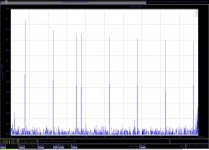
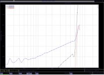
I measured the MPP at 20Hz, 1kHz and 20kHz with varios input levels.
The RIIA in in action with these measurements. I do not have a passive inverse RIAA at hand momentarily but i plan to build one and then do the measurements again. Gain is very high in this measurements at 20 Hz (+84dB, e,g. 64dB plus 20dB RIAA) and i could not reduce the output voltage with the equipment that i had on hand spontaniously, so take this measurement with a grain of salt.
What do this measurements show?
Basically that the MPP can not swing much more then 5V cleanly at any frequency. so overload margin is around 20dB with a cartridge that puts out 0.5mv at cruising level. distortion is only 2nd harmonic at low level and rises with level. higher harmonics are showing up monotonically at higher levels. i found this typical with open loop designs. designs with high feedback seem to behave a little different in my experience because they stay clean until a certain level and go into overload more suddenly. if that is a disadvantage or not i do not know. i think overload has simply to be avoided. Does that lead to the conclusion that open loop designs have better low level resolution and feedback desigs have a resolution boundary ? i think that is much to early to say and neads more reseseach.
If good enough is not good enough the remedy whould be simple if you want more overload margin: the gain structure in the MPP could be changed for example giving the intrumentation amplifier more gain and build an outputstage with more voltage swing unburdining the inputstage. distortion in the MPP (high level distortion, that is) comes mainly from the inputstage. this is contrary to the observation that in other designs distortion comes more from the following stages that have to swing more voltage.
by the way i ran the MPP including the op amps on a +- 12V supply.
Attachments
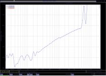
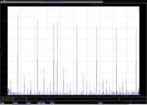
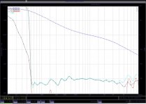
at last i show a sweep from 20 Hz to 20kHz of a level of 1V RMS @ 1kHz.
The MPP runs out of steam under 60Hz because the output voltage is over 5 V. this will not happen in reality because low frequencies are suppresed on the record.
distortion is mainly 2nd again. some 3rd harmonic is intruding over 6kHz due to the ballanced-parallel symmetric nature of the design. i hope it is high enough in frequency and low enough in level to not be audible. lumba will of cause complain that the bad nature of this circuit will bite it`s horrible teath into his delicate ear tissue.
you may wonder why the 3rd harmonic does not show in the 20kHz overload plot. it is because my 96kHz-24Bit A-D converter simply does not capture it. this tone is at 6okHz so it is suppred by the steep 48kHz anti aliasing filter, not to talk about the Shannon theorem.
Attachments
I wouldn't be happy with this kind of performance, but for open loop it's about what one can expect.
I would be more concerned about those 20dB headroom. To my experience, that's totally insufficient. Try and build one with 26dB (that is, 10V swing) and give it a shot. Play a used record and you'll hear a huge difference out of the bat.
I would be more concerned about those 20dB headroom. To my experience, that's totally insufficient. Try and build one with 26dB (that is, 10V swing) and give it a shot. Play a used record and you'll hear a huge difference out of the bat.
I take your comment serious and will try the improved version. Thanks for contributing.
i do this for fun triggered by Malkolms notion that there may be a resolution boundary in feedback circuits. anyway i will give my best to improve the circuit further and as i already mentioned feedback could be added too. My commercial products have very low distortion, need no selection and are competitively priced if not cheep because we build them by hand (even soldering) in Germany. Anyway you are an inspiration for me and i find your approach thorough. Thank you for sharing this hobby (yes, i think this is still my hobby although i make money with it) with such talented people.
i do this for fun triggered by Malkolms notion that there may be a resolution boundary in feedback circuits. anyway i will give my best to improve the circuit further and as i already mentioned feedback could be added too. My commercial products have very low distortion, need no selection and are competitively priced if not cheep because we build them by hand (even soldering) in Germany. Anyway you are an inspiration for me and i find your approach thorough. Thank you for sharing this hobby (yes, i think this is still my hobby although i make money with it) with such talented people.
one little thing that bugs me. syn08 i have studied your website again and you talk about
32 V Peak to Peak output capability of your best phono stage. this is quite a spectacular reading compared to my meager 5V or 10V in the improved version. first i use RMS readings and second i measure only only one side of the voltage swing. so that translates into 5 x 2 x qrt2 = 14.1 V P-P and 10 x 2x qrt2 = 28.2 V P-P. i run the circuit on +-12V supplies ( also the OPAs but i may change to +-15V) out of reasons i did not discuss here so more is simply not possible without redesigning the gain structure and the output amp again. Anyway, for the time being i won´t make any big change until i have the full measure sound wise. i know, i should be forbidden to listen to it. it is simply not good enough.
32 V Peak to Peak output capability of your best phono stage. this is quite a spectacular reading compared to my meager 5V or 10V in the improved version. first i use RMS readings and second i measure only only one side of the voltage swing. so that translates into 5 x 2 x qrt2 = 14.1 V P-P and 10 x 2x qrt2 = 28.2 V P-P. i run the circuit on +-12V supplies ( also the OPAs but i may change to +-15V) out of reasons i did not discuss here so more is simply not possible without redesigning the gain structure and the output amp again. Anyway, for the time being i won´t make any big change until i have the full measure sound wise. i know, i should be forbidden to listen to it. it is simply not good enough.
one little thing that bugs me. syn08 i have studied your website again and you talk about
32 V Peak to Peak output capability of your best phono stage. this is quite a spectacular reading compared to my meager 5V or 10V in the improved version. first i use RMS readings and second i measure only only one side of the voltage swing. so that translates into 5 x 2 x qrt2 = 14.1 V P-P and 10 x 2x qrt2 = 28.2 V P-P. i run the circuit on +-12V supplies ( also the OPAs but i may change to +-15V) out of reasons i did not discuss here so more is simply not possible without redesigning the gain structure and the output amp again. Anyway, for the time being i won´t make any big change until i have the full measure sound wise. i know, i should be forbidden to listen to it. it is simply not good enough.
HPS 3.1 and HPS 4.0 are in fact allowing 40Vpp at the output. Supplies are +/-22V and I'm using 44V opamps (OPA552, LT1115, OPA2604, LME49870). This leads to a 32dB headroom, at all frequencies in the audio band (due to the way the 60dB gain is split between the head amp and the distributed RIAA correction).