For example i published this circuit at the biginning of my thread that also uses current soures for more gain and could be a candidate for AIOG.
Dear Joachim,
looking at this circuit please let me comment that pots P2, P3 should
probably be connected to the emitters of T5, T9 and not their bases
in order to ease offset adjustment (but one pot and a change in one
resistor is sufficient). P1 should be substituted by a 10 Ohms pot (or
R8, R10 changed to 10 ohms) in order to drive the Fet pairs equally.
Where can I find the "harsh critique because of potential DC into the
cartridge"? I don't see the point, because it will simply not happen in
a working circuit. This may be the reason for your care in residual input
offset (as opposed to switch on/off transients), but in my opinion the
leftover of some dc millivolts is not worth considering. Any need for
adjustment means additional complication "Bias stability" is a different
matter.
I also did not see "Second Return From The Abbys". But anyway, for
a general discussion on analog circuit design this is probably not the
correct thread.
Best,
A.
Dear A. !
You are right and i did that changes in various disguises later. This circuit is what i call an Alfa. A concept that was never build. This thread get´s rather long and i myself have lost track of all the details. I just wanted to show that i had that constant current idea too and actually optimised it in my Discrete INA. I was searching today for half an hour to present my transimpedance solution again but i did not find it so far. My 8G stick has crashed and i lost a lot of material. It was posted somewhere here so i will find it.
Actually i own an Essex equalizer that has AIOG transimpedance RIAA and also the LC Audio Phonostage has that but not AIOG. The only circuit i made is the one i can not find momentary. Syn08 was the one that bugged me about even tiny amounts of DC so is the opinion held by Douglas Self. Ones in the mind of people put in from authorities like that it is hard to argue if you do not find a solution. Actually i am on your side and my transimpedance circuits sounded fine without Bias Cancelation. I actually started to make a survay if that effects distortion because theoretically the DC could drive the coils out of the optimal position against the magnet system and cause 2nd harmonic. I build a circuit that could insert various amounts of DC but that experiment was not continued because of time constrains. The circuit i have now can do that too but now having solved the issue my motivation is little. I could use a record with say a sine of 1kHz and measure distortion. Another idea i had whould be to simply raise down preasure a bit and push the coils back into the optimum position. Miss aligned cartridges could be compensated that way too.
Thanks for your contribution.
P.S. Although i experimented a long time with DC transimpedance stages ( power on-off, only positive power, only negative power etc.) i never fried a cartridge. I am still using the same Titan i i use for over one year now and it sounds just fine.
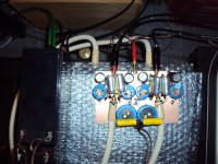
I made a simple MC Phonostage with the new input arangement. I call it Nobrainer because it is so simple. A lot of input transistors can be used. A BC550 / BC560 pair gives around the noise of a 70 Ohm resistor in this arangement. If you parallel two plus two it goes down to 35 Ohm, around the noise of a modern low noise Opamp like the LT1115. If that is not good enough there are a lot of choices presented here before. No sorting is needed because idle current and input offset can be adjusted. The amount of idle current is somewhat limited by the constant current Fets so use one with a high Idss if you want lots of Bias. The Fet i am using has Idss of around 30mA. I build a version with 3.5mA on the input transistors and got the noise down to 19 Ohm
equivatent with 7 cent transistors if you buy them from a trustworthy vendor. In fact i bought them for 4 cent each from Reichelt. They only thing i found was that they had not much current gain ( around 200 ) but this is not of consequence in this circuit. A common base stage has a current amplification of around one and i heard that lower Hfe is good for high early voltage. I measured the -3dB response going up to 2.2Mhz in the input stage driven by a 6 Ohm resistor that mimics my cart. This is more then enough and i had no trouble with radio interference, maybe because the low input impedance. Stability is not a problem too because it is an open loop circuit.Yes, i know, NFB circuits can be made stable too. I did that in my discrete INA. Even at high very high volume i can only hear a very faint and soft hiss. At the volume i usually listen too ( my wife falls out of bed when i do that and she is 3 doors apart and 2 strories up in my rather big house ) i can not hear the noise in our extremely quit environment. Allen Wright was complaining when i listened that load when he visited me last so let´s keep the church in town as we say here. Be sure that not more then 10V C-E voltage develops over the input transistors or you get a new source of noise. Ask Piglets Dad about that. I use a simple R-C filter in my setup and it proved adequate. Use your creativity to improve on that. Capacitance multipliers, Szikley pairs, shunt regulators, you name it. I delibarately use AC coupling and no servos for the least posible amount of silicon in the signal chain. I get tired of arguing what is better : elegant simplicity or heavy and inteligent engineering. I got the impression that both aproaches can work subjectively and this is a example how somebody with not much experience can do something that does not hurt the ears with an absolute minimum of money and efford. I call that DIY. Tomorrow Stig Björge of Lyra visits me and Martina Schöner from Garrrard - Loricraft - L´Art du Son will come too, so let´s do them make the subjective accessment. They have both no idea what i did.
Some more expanation : i do the 75usec first with just a cap to ground. I have tryed that many times and like the result better then putting the 75usec in the second stage. The advantage of my choise is that the second stgae is not taxed as much with energy rich treble that can come from scratches and dirt on the record. For the second stage use a precission Opamp to avoid offset. Most audio Fet devices like the OPA134, OPA627, OPA827, OPA1641 work well here so do a surpising amount of Bipolars. I tryed
an NE5534A and offset was under 2mV. See what Douglas Self has to say about this bargain king. Common mode distortion is low in my arangement beacuse i drive the opamp with a nearly fitting output impedance. Colour me blind but i am happy with this circuit.
Attachments
Usrc
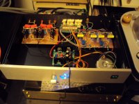
Today i finished another preamp for a friend. I call it USRC for Ultra Simple Remote Control. I used my USAIOG phonostage and my "new" USLS ( Ultra Simple Line Stage ).
Actually there is nothing new with this line stage. Just a good Opamp with series feedback.
I choose the feedback resistor value to be able to insert a current feedback Opamp like the LME49713 which i like much. Actually i build this version with an LME49710 that is a conventional voltage feedback type of modern design. With this OP i did not need a servo or a coupling cap. DC offset is under 0.5mV and no switch on and off transients.
Stil this preamp is not without some comfort. It has a passive output that can feed a subwoofer and a switchable filter that takes of some burden from the main speakers when the sub is connected. I use a Tent Labs volume control that i find comfotable and transparent sounding. Actually i had some trouble first. There was a terible hum and during experimentation i somewhow distroyed the micro processors in the volume control. I drove to Guido Tent that did repair and tried to fix the hum problem. Actually
after his modification it looked good on the scope but back home the hum was back too. I needed two full days to find the problem. The Tent Labs has a floating supply that i supplied from the transformer of the Placid PSU i am using. That created a hum loop.
Why i do not know but now that i supply the volume control board from a seperate transformer the hum is gone. Actually that pre does work well dispite it´s simplicity.
I think one of the reasons is that i choose good quality parts and took care in the PSU and generous lokal decoupling. Anyway, if you need a quick and easy fix this USRC is not the worst you can do.
Attachments
Hi,
First can i say a big thankyou to Joachim for sharing his ideas and making these circuits available to the many less technicaly minded DIYers who i am sure are quietly studying this thread, with keen interest.
I first became interested in zero loop feedback trasimpedance riaa equalisation after reading the article published many years ago in HFN, Sounding the Charge, at the time i thought what a very interesting circuit
I did manage to build a similar riaa equaliser, but bias stability, and adequate gain were always a problem with one stage, not to mention the batterys, so eventually i gave up and stuck to more conventional forms of riaa eq.
This thread has kind of rekindled my interest,
Basicly my question is this, is it possible or whorthwhile to attempt a 2 stage phono equaliser based on the high Z version, with split transimpedance riaa eq between stages followed by a buffer?
Really just to explore the benefits of fully passive riaa eq and no negative feedback in all stages.
Has anyone tried this?
Thanks.
Why i do not know but now that i supply the volume control board from a seperate transformer the hum is gone.
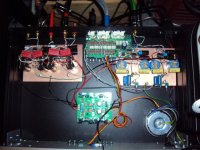
That is exactly why I used 2 power supplies in the RIAA/ADC pre amp, one for the RIAA amp and one for the ADC. Using separate power supplies breaks all possible ground loops between major building blocks. Signal ground and power ground will be separated totally, and thus there is no way for power currents to flow though the signal (ground) lines.
Regards,
Frans.
Hello Velvetsunrise ! The High Z MPP can be modified that way. I would rather prefer a one stage aproach because much higher Gain-Bandwidth products are posible today compared to the Essex Equalizer. I am very busy with some comercial work at the moment so give me some time and i show some posible solutions.
In fact i am working on a transimpedance stgae at the moment so i had to study that option in detail anyway.
In fact i am working on a transimpedance stgae at the moment so i had to study that option in detail anyway.
") ,
, This is an example of a two stage transimpedance RIAA by Mr.Evil. In a strict sense this is no transimpedance RIAA because the filters are not fed by constant current sources so the drain resistors form a voltage devider with the filters. I will show a posible solution soon based on my High Z MPP. Nevertheless i find this circuit elegant and effective.
Attachments
MPP Nova Transimpedance RIAA
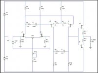
Here comes my solution for a one stage transimpedance RIAA. The circuit is a modified MPP Nova. The collector resistors of the input cascode are substituted with current sources. The input stage works on 14mA and the folded cascode on 21mA. The current sources give much more gain. I have shown two alternative versions to do the RIAA.
One is used by the Essex Equalizer and one is the LC Audio version. I have not calculated this values and may come up with my own version. I have not build this circuit but it should work. The buffer can be trimmed for offset.
Attachments
Joachim Gerhard;2228572 I think you like the circuit because it is discrete and straight forward.[/QUOTE said:Yes, and MOSTLY because it doesn't use NFB.
Regards, Allen