I am in India in vacation and had some time today. Just for fun I am working on a modern version of the Nordholt & van Vierzen pre-pre from 1980.
The circuit is AC coupled over some relatively big sized Elcaps. One could make a parallel symmetric version with servo that avoids this problem. Noise should be 3dB lower with less second harmonic. On the other hand, dominating second harmonic of a single ended circuit is not such an audible problem. Geldes goes so far that he things that the ear ignores second harmonic because of masking. Anyway, I made enough parallel symmetric circuits, so I need a little break and try this one.
The circuit is AC coupled over some relatively big sized Elcaps. One could make a parallel symmetric version with servo that avoids this problem. Noise should be 3dB lower with less second harmonic. On the other hand, dominating second harmonic of a single ended circuit is not such an audible problem. Geldes goes so far that he things that the ear ignores second harmonic because of masking. Anyway, I made enough parallel symmetric circuits, so I need a little break and try this one.
Attachments
Elektor style picture of the Noldholt circuit here :
https://www.diyaudio.com/community/threads/mpp.154210/page-558#post-6333900
https://www.diyaudio.com/community/threads/mpp.154210/page-558#post-6333900
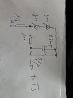
For output at mid supply (9V) output, ignoring the small drop over the 10k, it should drop about 4.5V with 10mA?I think for beginners , this is a nice circuit to study the currents, the voltages and the impedances. How whould you set the unmarket resistor to get 10mA in the output transistor ?
PS Enjoy your holiday!
Jan
I now see you take the output from the C, I thought it was taken from the E. My bad.Two currents flow out of the unmarked resistor. Most of it flows into the output transistor. The second part supplies the base current of the input transistor. I choose input transistors with ß of 450 ( in Germany we say hFE, or do we ? ).
OK, 2nd try ;-).
10mA CS puts E of input Q at 10mV, disregard, puts B of input Q at ~0.65V.
Through 10k flows 10mA/450hFE = 22uA so across 10k = 0.22V
So E of output Q is at 0.65 + 0.22 = 0.87V.
Across unknown Re = 9V (supply) - 0.87 = 8.13V at 10mA = 813 ohms.
That somewhat right?
Jan
Last edited:
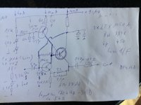
If there would be a wire instead the 51R and 56n RC network it is only a Sziklai darlington (compound darlington) together with a current source.I am in India in vacation and had some time today. Just for fun I am working on a modern version of the Nordholt & van Vierzen pre-pre from 1980.
The circuit is AC coupled over some relatively big sized Elcaps. One could make a parallel symmetric version with servo that avoids this problem. Noise should be 3dB lower with less second harmonic. On the other hand, dominating second harmonic of a single ended circuit is not such an audible problem. Geldes goes so far that he things that the ear ignores second harmonic because of masking. Anyway, I made enough parallel symmetric circuits, so I need a little break and try this one.
In the 80s elektor had a magazine for july/aug each year a lot of easy circuits. As I know, the input transistor was a BFW16 with low Rbb in base-emitter direction.
What actually is the aim of the above mentioned RC network ?
Actually since both transistors are at 10mA, the 1R resistor carries 20mA so the E of input Q sits at 20mV, not 10mV.
Not that it makes a big differences in the grand scale of things ;-).
@Tiefbassetc: Does that not set the gain, it is the feedback network. In the 2nd circuit, 22R and 1R?
The C looks large but it is // to 22R, so RC time still small. Intersting circuit.
Jan
Not that it makes a big differences in the grand scale of things ;-).
@Tiefbassetc: Does that not set the gain, it is the feedback network. In the 2nd circuit, 22R and 1R?
The C looks large but it is // to 22R, so RC time still small. Intersting circuit.
Jan
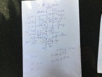
I have worked on the modified circuit a little and have drawn it better. RB can safely be 68kOhm because hFE of the ZTX1051A is 10x higher then in the BFW16A. Now come new interesting questions. How high is the input Impedance and how high is the overload margin ?
Attachments
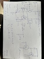
22R // 0.1u seems like ~72kHz high pass, rolling of the gain from 23x at midband to 1x at HF.It is a 50kHz lowpass. The resistors set the gain. With a short it is a buffer.
Maybe swap the pos of the 1.5k and the LEDs around T3?
I think Zin is 68k since the feedback bootstraps T1E to the signal level.
Output C is at 240mV DC or so so max Vout is lower than 480mV pk-pk.
Linearly 150mVrms?
Edit: I don't know how to calculate noise level.
Jan
Last edited: