No, i do Not Wang to make a product with the IF3602. This is for fun. The pictures Shows something that aride my curiosity besides high gain.
O.k. that impression arose in your #11535 posting.
What about “matching the channels “ that you mentioned in this same posting?
Hans
I came late to this thread and never realized you had a commercial goal in mind with this amp.
In that case I could give you some additional tips.
1) For a commercial product to stand off from the crowd, overload margin @20Khz should be at least 30dB or circa 158mV@20Khz for the 0.5mV@1Khz standard.
But that is easy to achieve.
The current design has the whole Riaa correction in one go, directly after the first stage, meaning that after having amplified the MC signal with the IRF3602, it will be attenuated by 40dB @20Khz, bringing it almost back to the original MC output level.
That’s why the noise performance of the second stage is now so critical.
However when you only apply the 75usec pole at this stage, the signal at 20Khz will only be attenuated by 20dB, making it possible to reduce the gain of the first stage a bit to achieve this 30dB OLM without any noise problem in the second stage.
Then between the second and the third stage the 3180usec and 318usec pole zero correction has to be placed and voila, there you are.
2) the second tip I would give to keep the product top notch, is to give it not only a SE but also a differential output. An OPA1632 instead of the OPA1652 will give you exactly that.
Then a question: what exactly do you mean with “matching the channels”.
Gain is set by resistors and not by the dual fet. Only the input capacity can vary from one fet to another, but an MC amp can easily have an input capacity of 1nF, so by adding the proper cap value up to 1nF this seems no problem.
Hans
Where would you place the cap to achieve the 75us pole in the 1st stage ?
Where would you place the cap to achieve the 75us pole in the 1st stage ?
Leave it exactly where it sits now.
Only the two other time constants have to be shifted to after the second stage.
Hans
I understand that the gain of the input stage is set with the two drain resistors.
That is after trimming the IF1602. I was concerned about differences of the two halves of it but now I think that it does not have much influence on the noise and gain.
When using the pot value of 10R with a 20R resistor in par. to keep the 6R6 value used so far, the position of the trimpot has no effect on gain or noise, because the impedance of the current source is so much higher, making it “invisible”.
Only the effective 6R6 of 10R//20R determines gain.
Hans
Where would you place the cap to achieve the 75us pole in the 1st stage ?
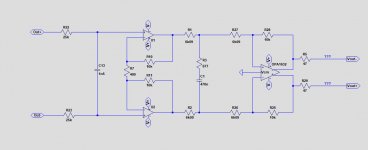
To give you an example, this is what I meant.
R7, R25 and R28 optional to set the gain according to your taste.
I have also added the zipped OPA1632 model for your convenience to be unzipped in the same directory as your .asc file.
Hans
P.S. When you don't like the 1632, this can also be done with the OPA1652 SE version, only R1,R2, R26 and R27 have to be recalculated.
.
Attachments
Last edited:

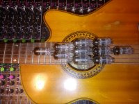
This one is even better if you have the cash. The glass ball talks to me that only 65.000 where made.
That is probably the most unobtanium of the super gm tube family.
Others are WE437A and equivalent STC 3A/167M. I've used the 3A/167M in the
past but they suffer similar probs to the Russian counterpart being microphonics and large gm variance.
Moved on and developed other solutions where high gm was required.
TCD
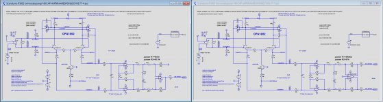
In case it could help finding a proper final design, here two versions, the left one SE out and the right one SE + Diff out.
Both have the maximum possible 61.8dB@1Khz SE gain with the used +/-15V supply. The right one has twice as much with 67.8dB Diff gain.
Maximum input at 20Khz is 115mV, or 20Log(5mV/115mV) = 27.2dB OLM for the standard 0.5mV@1Khz MC Cart.
All three stages have a gain exactly as such that the maximum output right before clipping is achieved simultaneously at each of the 3 stages at the most critical 115mV@20Khz.
For the frequencies below 20Khz, OLM is between 27.2dB and 27.8dB.
Hans
.
Attachments
6C45P.
Here you go, high gm tube porn, check the thickness of anodes,
built like a tank.
TCD
Attachments
I came late to this thread and never realized you had a commercial goal in mind with this amp.
In that case I could give you some additional tips.
1) For a commercial product to stand off from the crowd, overload margin @20Khz should be at least 30dB or circa 158mV@20Khz for the 0.5mV@1Khz standard.
But that is easy to achieve.
The current design has the whole Riaa correction in one go, directly after the first stage, meaning that after having amplified the MC signal with the IRF3602, it will be attenuated by 40dB @20Khz, bringing it almost back to the original MC output level.
That’s why the noise performance of the second stage is now so critical.
However when you only apply the 75usec pole at this stage, the signal at 20Khz will only be attenuated by 20dB, making it possible to reduce the gain of the first stage a bit to achieve this 30dB OLM without any noise problem in the second stage.
Then between the second and the third stage the 3180usec and 318usec pole zero correction has to be placed and voila, there you are.
2) the second tip I would give to keep the product top notch, is to give it not only a SE but also a differential output. An OPA1632 instead of the OPA1652 will give you exactly that.
Then a question: what exactly do you mean with “matching the channels”.
Gain is set by resistors and not by the dual fet. Only the input capacity can vary from one fet to another, but an MC amp can easily have an input capacity of 1nF, so by adding the proper cap value up to 1nF this seems no problem.
Hans
Perfect... I would like to sim those but can not see the values and placement of R1 R2... etc.In case it could help finding a proper final design, here two versions, the left one SE out and the right one SE + Diff out.
Both have the maximum possible 61.8dB@1Khz SE gain with the used +/-15V supply. The right one has twice as much with 67.8dB Diff gain.
Maximum input at 20Khz is 115mV, or 20Log(5mV/115mV) = 27.2dB OLM for the standard 0.5mV@1Khz MC Cart.
All three stages have a gain exactly as such that the maximum output right before clipping is achieved simultaneously at each of the 3 stages at the most critical 115mV@20Khz.
For the frequencies below 20Khz, OLM is between 27.2dB and 27.8dB.
Hans
.
Can you post a pdf or a bigger image Hans ?