…
In a balanced line receiver application, you do not know the impedance's …
…
But in the circuit at hand you do know, the output impedance of the driving circuit is, in both legs, neglectable (compared to the 6.666...kOhm impedance of a perfectly set of 10k and 10k/3 resistors).
And yes, use at the least 1% or even better resistors in this type of circuit. In any case even at 10% it will be an improvement from the all equal resistor solution (as in general use).
But impedance matching is, especially in the current (modern) high radiation (wifi, telephone, and what more …) environment
I agree when you refer to the INA’s plus and minus inputs, they prefer to see the same impedances, especially bipolars. The same bias current from the opamp’s inputs will cause different effects when seeing different impedances.
When you don’t agree, please come with a real example avoiding to turning in circles with just words, because I don’t see any reason how CMRR can be improved with unequal resistors.
Hans
P.s. When you want to fight radiation, always start at the input and not at a point where the signal has already been amplified by 60 dB.
Hans I stand corrected, the all-equal-resistors version presents unequal load currents but does not decrease CMRR; for best CMRR the resistors should all be equal. Funny how you can mix up things if you don't look at them for several years... Apologies for the confusion.
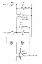
I just reviewed my autoranger documentation and the actual used circuit to convert bal to se is as attached. This is the circuit I discussed with RME. The earlier shown circuit is for the RMS measurement chain were requirements are more relaxed.
For inspiration, see Kirkwoods exposé at https://www.edn.com/audio-line-receiver-impedance-balancing-using-a-2nd-diff-amp/
His fig 4 is a neat way to impedance-balance the two balanced-to-single-ended converter inputs, and with that, equal load currents.
Jan
Attachments
Last edited:
Does the schematic in post 11446 have equal input impedances/currents ?
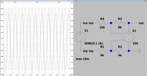
Maybe this will tickle your fancy.
Works fine for known impedances of the source, if you know the source impedance then subtract this value from the input resistor value, and in the case at hand just ignore the output impedance (of the driving circuit) it is near enough to zero (compared to the 6.666... kOhm mixed resistor circuit it's impedance)
Attachments
Last edited:
Jan,@ Hans: if the load currents are unequal, there is an unequal voltage drop on the output impedance of the two driving nodes. With the unequal resistor pairs, both the voltage drop over Zout as well as the load currents are equal, promoting CMRR.
Jan
I don’t want a discussion who’s right and who is wrong.
When we don’t agree that’s fine.
But one last try: different load currents giving unequal voltage drop at the driving side is true, but this impedance is independent of the load.
Say for instance Rout is 10R at a certain frequency.
And in this example we have two 3k3 resistors on one side and two 10k resistors on the other side.
Then effectively we would get 3k01/3k and 10k01/10k.
Now CMRR has been reduced to -33.9 dB.
Hans
My model of OPA1652 does not work as expected.
To make the circuit work I must reduce the drain resistors from 400 to 100 and there is too much current flowing out of the opamps.
That is sometimes a problem with these models.
But UniversalAmp2 with full selectable parameters gives you another possibility to get what you want.
And even a working model never gives 100% of the real thing but is mostly a coarse approximation.
Hans
what about opamp compensation.... should I be worried about it ?
Of course - especially with this super high capacitance Jfet pair.
This is a pretty standard mic pre / tape repro head circuit and it is always
implemented with a pole around first opamps which take the IP devices (Jfets)
out of circuit at VHF.
TCD
Unequal load currents to differential signals but equal load currents toHans I stand corrected, the all-equal-resistors version presents unequal load currents but does not decrease CMRR; for best CMRR the resistors should all be equal. Funny how you can mix up things if you don't look at them for several years... Apologies for the confusion.
common mode signals. This does not seem to be well understood here.
For inspiration, see Kirkwoods exposé at https://www.edn.com/audio-line-receiver-impedance-balancing-using-a-2nd-diff-amp/
His fig 4 is a neat way to impedance-balance the two balanced-to-single-ended converter inputs, and with that, equal load currents.
Jan
Yes, that is the Cohen double balanced circuit shown earlier.
TCD
To add even more confusion :
In general, the resistors of the two "legs" need not to be equal.
But the quotient of resistor values of positive leg and negative
leg has to be the same in order to maximise CMRR.
Now what about the input impedances ? Formula please, no sim.
In general, the resistors of the two "legs" need not to be equal.
But the quotient of resistor values of positive leg and negative
leg has to be the same in order to maximise CMRR.
Now what about the input impedances ? Formula please, no sim.
To add even more confusion :
In general, the resistors of the two "legs" need not to be equal.
But the quotient of resistor values of positive leg and negative
leg has to be the same in order to maximise CMRR.
Now what about the input impedances ? Formula please, no sim.
Exactly. No confusion, same applies, equal CM impedance.
TCD
Didn't I learn you how to do that ?
Anyhow, for noise calculations you can also use UniversalOpamp2 at the end of the opamp list and enter for the OPA 1652:
En=3.8e-9 In=0
Enk=400 Ink=0
GBW=18Meg Slew=10Meg
Hans
What are En and Enk ?
Funny discussion about differential amp impedances. Could have been avoided if an integrated type would have been used right from the beginning ;-) (what imho makes much more sense anyhow)
Out of interest, I put the earlier discussed BJT version next to JFET version, as they are not the same. Or did I miss something?
Circuit attached fyi. (I just took some random transistors to understand the circuit)
Boris
Out of interest, I put the earlier discussed BJT version next to JFET version, as they are not the same. Or did I miss something?
Circuit attached fyi. (I just took some random transistors to understand the circuit)
Boris
Attachments
True. It’s important to understand how (integrated) analogue circuitry works. And I have learned something from that discussion.
I only had the impression that two different things were discussed here:
-the textbook differential amp (substractor) which has 4 equal resistors which represents equal common mode resistance in each leg, which is necessary for high CMRR
-and the approach with unequal resistors (1:3 ratio) in each leg which balances the differential mode input impedance. If this has any advantage for the audio signal I cannot say, but its an interesting variation of the circuit.
The general textbook message is resistor value ratios have to be equal
(you can set up the subtracting circuit with any gain different from 1).
Others still have to demonstrate which resistor scaling would be optimum
for "equal input impedance / current" on the positive and negative side.
(you can set up the subtracting circuit with any gain different from 1).
Others still have to demonstrate which resistor scaling would be optimum
for "equal input impedance / current" on the positive and negative side.