I wondered why the noise with the dual fet was relatively high, as I said earlier, good but not excellent.
That's why I went into further details and found that U3/U4 where the major cause.
The LT1056 is not at all suited to be used at this position.
When using a OPA1652 or OPA1656 for U1 to U4, A-weighted noise can be reduced by a spectacular 8dB.
This will bring EIN with 0R source from 0.7nV/rtHz to 0.3nV/rtHz and that is excellent.
Hans
PS:
The input is referenced to gnd through R4 R5 and I see you did not object to that. these two resistors (that could be much higher in value in this case) will not obscure the balanced input operation so I believe that connecting c13 and c1 to gnd does also not affect balanced operation.
Also it is much simpler to match the two 30n caps instead of trying to much a single 15n cap.
But it can be done as per the evo8.73 sim below
Attachments
1) so better use well matched resistors. With 400/401 I only get 2.7V before the INA and after the INA 140pV.1) C15/C16 are DC blocking caps but also part of the riaa compensation.
If removed, the riaa filter must be modified to cope with the extra bass boost.
The circuit works without them as long as the 1st stage components are all extremely well matched.
If there is a small mismatch (for instance R2 = 401 instead of 400) the circuit still works but we have already 6V offset in the output.
If the mismatch is more serious (R2 = 405 instead of 400) the circuit does not amplify and we have 13V offset in the output.
Anyway this was a very good point as I also do not like the big 10u caps but something must be done to avoid collapsing so I added two small 100n caps after the RIAA filter, recalculated the input resistors on the RIAA and the circuit works flawlessly now.
2) You can remove this connection to GND and will not see any difference in the circuit operation. I did follow the instructions found here Still More Phono Preamps
"On the other hand, adding just one more capacitor and referencing the 2122Hz pole to ground will preserve a much more accurate final equalization, in spite of slight imbalances. (This is something will not show in a SPICE simulation, unless you go looking for it, as SPICE parts come perfectly matched.)"
3)I did see better current matching in the output buffer with this resistor combination suggested by Frans......
Below the new
2) this connection will inject ground noise into the signal.
3) current matching is no issue, it does not bring any benefit.
Hans
I had a look at the circuit in #11410, and have a number of comments:
1) C15/C16 have no function, they can be omitted saving quite some PCB space.
2) The junction between C2/C3 and C13/C1 are connected to Gnd, this has no function.
3) Output amp U8 has 3k3 and 10K resistors, more logical would be all four 3k3 or all 10k.
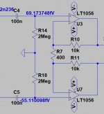
When measuring the equivalent input noise with a 0R source resistance, I get 0.71nV/rtHz A-Weighted which is good but not excellent for this very expensive dual Fet.
With a 10R source EIN becomes 0.73nV/rtHz A-weighted.
See calculated input noise below with 10R source.
Hans
.
I wondered why the noise with the dual fet was relatively high, as I said earlier, good but not excellent.
That's why I went into further details and found that U3/U4 where the major cause.
The LT1056 is not at all suited to be used at this position.
When using a OPA1652 or OPA1656 for U1 to U4, A-weighted noise can be reduced by a spectacular 8dB.
This will bring EIN with 0R source from 0.7nV/rtHz to 0.3nV/rtHz and that is excellent.
Hans
I am using LT1056 just for simulations. Chosen because it is a jfet input opamp like the 411....
Would you care to share the OPA1652 model ?
Yes, the circuit works with 401 / 400 but not with 405/400.... must be matched.
But I believe it will be very difficult to match the jfets and that might cause aditional difficulties. The new C4 C5 100n are small, can be used to form a low pass anti rumble filter and avoids any issues with IPS mismatching.
But I believe it will be very difficult to match the jfets and that might cause aditional difficulties. The new C4 C5 100n are small, can be used to form a low pass anti rumble filter and avoids any issues with IPS mismatching.
Where can we read about this ? Please at least one published
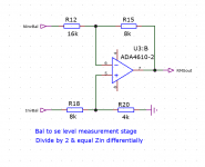
example of an instrumentation amp with different "legs".
See attached, from the autoranger. A trick I learned from Matthias Carstens of RME fame!
This way you draw equal currents from the diff stage which helps CMRR.
Jan
Attachments
I just noted that he should check the input currents at both legs (using the simulator it's very easy).
Yes you really must check it. Its counter-intuitive.
Jan
See attached, from the autoranger. A trick I learned from Matthias Carstens of RME fame!
This way you draw equal currents from the diff stage which helps CMRR.
Jan
Jan,
Can you think of any reason why equal currents would lead to better CMRR, and why all INA manufacturers promising very high CMRR are using equal resistors ?
Hans
... Anyway this was a very good point as I also do not like the big 10u caps but something must be done to avoid collapsing so I added two small 100n caps after the RIAA filter, recalculated the input resistors on the RIAA and the circuit works flawlessly now.
...
You loose input bias for U3, U7 this way (schematic of post 11440).
See attached, from the autoranger. A trick I learned from Matthias Carstens of RME fame!
This way you draw equal currents from the diff stage which helps CMRR.
Jan
I asked for a "published example". May be a link would be sufficient.
On the other hand, as you frequently say, Extraordinary claims require
extraordinary proof. This schematic is not enough ..
You loose input bias for U3, U7 this way (schematic of post 11440).
Please explain.... do I need to reference U3 and U7 inputs to gnd ?
I am using LT1056 just for simulations. Chosen because it is a jfet input opamp like the 411....
Would you care to share the OPA1652 model ?
Didn't I learn you how to do that ?
Anyhow, for noise calculations you can also use UniversalOpamp2 at the end of the opamp list and enter for the OPA 1652:
En=3.8e-9 In=0
Enk=400 Ink=0
GBW=18Meg Slew=10Meg
Hans
Jan,
Can you think of any reason why equal currents would lead to better CMRR, and why all INA manufacturers promising very high CMRR are using equal resistors ?
Hans
As stated before, equal differential currents but unequal CM currents.
In a balanced line receiver application, you do not know the impedance's that are driving the receiver. Anything more than zero will result in Jan's circuit
having worse CMRR than an 'equal R' bal line receiver. This is due to mismatched CM impedances between phases causing CM to differential
conversion. Balanced studio wiring theory, ref whitepapers by Bill Whitlock
etc.
Once you start talking about distortions of both topologies things get a bit more complex. In Jan's circuit the summing opamp will likely have worse
CM distortion but this will depend how susceptible the opamp is to CM distortion. See Samuel Groners paper.
TCD
…
3) current matching is no issue, it does not bring any benefit.
...
But impedance matching is, especially in the current (modern) high radiation (wifi, telephone, and what more …) environment
Jan,
Can you think of any reason why equal currents would lead to better CMRR, and why all INA manufacturers promising very high CMRR are using equal resistors ?
Hans
As above, equal impedances will improve things, (and even earlier [more above ?
") ]) these are impedance circuits, not voltage or even current ...
]) these are impedance circuits, not voltage or even current ...
Last edited:
I asked for a "published example". May be a link would be sufficient.
On the other hand, as you frequently say, Extraordinary claims require
extraordinary proof. This schematic is not enough ..
@ as_audio: you can simply run a sim and see that with identical resistors, the currents are unequal.
@ Hans: if the load currents are unequal, there is an unequal voltage drop on the output impedance of the two driving nodes. With the unequal resistor pairs, both the voltage drop over Zout as well as the load currents are equal, promoting CMRR.
Jan