HDAM Schematic
Thank you for the HDAM schematic, where did you find it?
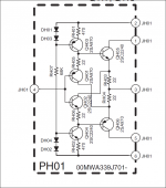
This is an elaborate emitter follower (no-feedback buffer).
This information was indeed missing in your post 10456
(Q 335, 336, 337, 338).
It appears that HDAM means Hyper Dynamic Amplifier Module,
but this is not an (op-)amp, just a follower.
At first I wanted to point out that the HDAM output in your pic
in post 10456 was mislabeled neg. input, this being incorrect.
If it was an opamp, the output would need to be connected to
the neg. input in order to act as a follower (so two pin numbers).
Now, knowing the ingredients of HDAM, the designation in pic
10456 is still incorrect, pin 4 should be output only, not neg. input,
which is missing in a buffer.
It is interesting to see a follower connected as a DC corrective
amp (kind of servo), Q337, 338 in pic of post 10456.
Note also that the circuit of the HDAM as shown here is practically
identical to the input stage of pic 10456, that means the circuit
could be set up with three of these per channel.
Last edited:
To answer your question someone sent me a PDF.
The schematic I posted is used mainly in front ends of gain stages. The more usual HDAM is attached below, which is used in the output stage.
To answer your other question I will have to check the complete schematic.
Jam
The schematic I posted is used mainly in front ends of gain stages. The more usual HDAM is attached below, which is used in the output stage.
To answer your other question I will have to check the complete schematic.
Jam
Attachments
The two HDAM modules are in function identical, one has a cascode, making it suitable for higher voltage operation, like the input-stage of a power-amplifier. (still have to regulate the CCS voltage down a bit).
Need to explore the HDAM servo a bit.
Also making tight-packed SMD modules with pins in the side, could be a good way to create own building blocks, The phono-stage is a good example, but it could also be set up as a no feedback line-stage ala Gain-wire or as a complete global-feed-back power-amplifier
Sabbath, match them to better than 1%, ideally match the input stage exactly across all four quads- tricky and needs to be done at operating temp. Use the opa627 for the servo and look at how you cool that shunT again.
I'm into double figures building these now and insane matching and zero pumping of input stage delivers major benefits precisely in the areas of stereo specificity and soundstage precision.
I'm into double figures building these now and insane matching and zero pumping of input stage delivers major benefits precisely in the areas of stereo specificity and soundstage precision.
I am working on a HDAM with J-Fet inputs...hopefully this will keep the offset down to a minimum and be able to direct couple without a servo...........
....or you an go really crazy and do something like the attachment ....maybe even calls for a new thread......what do you think Chris?
Jam
....or you an go really crazy and do something like the attachment
....maybe even calls for a new thread......what do you think Chris?Jam
Attachments
Last edited:
In the Marantz phono stage I do not really understand why the two hdam modules one in front of the other.... would you care to explain ?
There also seems to be a feedback loop with complex filtering attached ?
Talk about post 10456?
http://www.diyaudio.com/forums/analogue-source/154210-mpp-1046.html#post4284257
In the Marantz phono stage I do not really understand why the two hdam modules one in front of the other.... would you care to explain ?
There also seems to be a feedback loop with complex filtering attached ?
The second one is attached using a 100K/4700u filter and acts as a servo (looks like that).
.. as seen in post 10461 http://www.diyaudio.com/forums/analogue-source/154210-mpp-1047.html#post4285795.The second one is attached using a 100K/4700u filter and acts as a servo (looks like that).
The circuit in post 10456 http://www.diyaudio.com/forums/analogue-source/154210-mpp-1046.html#post4284257 is a phono amp with an elaborate "Diamond Transistor" input stage,
follower (Q335) and dc corrective amp (Q337). As seen in post 10460 http://www.diyaudio.com/forums/analogue-source/154210-mpp-1046.html#post4285697 the HDAM modules
used here are elaborate diamond followers, not opamps. Pin 4 is mislabeled in pic of 10456 as
neg. input, it is the output.
The whole thing is not easy to explain in detail and I will try only if requested.
As I said (just answered a question).. as seen in post 10461
Aye aye, sir.. as seen in post 10461 The whole thing is not easy to explain in detail and I will try only if requested.
aye aye, sir - Wiktionary, http://en.wiktionary.org/wiki/sarcasmHi Jam,
Oh my! You really must be bored to come up with that! Its too early in the day for me to think through it all. I wouldn't want to be the guy that had to match all those transistors!
Normally I would go for something a little less complicated. You only need enough to allow the signal path to be linear. I like the idea of using J-Fets, but you still need the BJTs to make the diamond buffer work as advertised. An input buffer using J-Fets might preserve the signal while also dealing with the bias currents from the BJTs. In a perfect world, the NPN and PNP bias currents would cancel, which automatically balances your DC offset. They should track reasonably well over temperature.
When I "throw together" a diamond buffer, an offset of 5 mV is common. Less than 30 mV if using different transistors for the output side. But then I am usually looking at something else other than DC offset, and 30 mV or less isn't anything to worry about when testing a circuit. I think in production you would need to use a zero DC offset op amp as a servo. Shifting the common base point to correct offset would be easy enough.
-Chris
Last edited:
aye aye, sir - ]
Frans, it was somebody else who requested some explanation.
I know you don't need any.
Frans, it was somebody else who requested some explanation.
I know you don't need any.
Just trying to push some buttons, sorry
I guess I needed that 
I am working on a HDAM with J-Fet inputs...hopefully this will keep the offset down to a minimum and be able to direct couple without a servo...........
....or you an go really crazy and do something like the attachment
Jam
That's neat. It has some rare concepts. I'd say it's definitely worth it's own thread, if only because it's unique. That alone may be a good reason to try it out.
Hi Chris,
Those are pretty good offset values you quote but what happens when your source impedance changes example the input was attached to volume control and we wanted to be direct coupled...............
To answer your first question ...Yes I was bored.
Jam
Those are pretty good offset values you quote but what happens when your source impedance changes example the input was attached to volume control and we wanted to be direct coupled...............
To answer your first question ...Yes I was bored.
Jam
Attachments

Last edited:
Hi Kean,
Maybe a new thread is called for.
Gentlemen,
On a different note I hope Joachim is doing better and wish him well. He started this thread and I believe it is one of the better threads in this forum and I don't want to see it end. I for one have learned a lot from it.
Jam
Maybe a new thread is called for.
Gentlemen,
On a different note I hope Joachim is doing better and wish him well. He started this thread and I believe it is one of the better threads in this forum and I don't want to see it end. I for one have learned a lot from it.
Jam
Due to earlier messages I'm going to say this (it was Joachims intention to keep this still). Joachim has been operated, on the hart, successfully and is recovering. He did not want to let any one know until he knew that it was done (and successful ). More news when I have news from him personally.
Frans.
). More news when I have news from him personally.Frans.