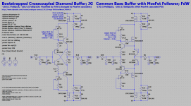
You may remember the improved diamond buffer, here it is again, together with a new 'Common Base'/'Allison' buffer. To explain:
I think it is a common base buffer due to the fact that the input transistor base is connected to the lowest impedance in the circuit (e.g. the output).
Joachim tells me it's a 'Allison' configuration, the signal goes in on the emitter and is controlled by the base, while drive for the mosfet is taken from the collector.
The collector of the input transistor is connected to the current source, so this is also a high impedance point.
The input resistance is about 500k (that is more then the diamond buffer, it has about 200k). The output resistance is about 100ohm, the diamond buffer has a output resistance more like 500ohm.
Some simulation results:
@1Khz Diamond -160 and -170dB (1st and 2nd harmonic)
@1Khz CommonBase -170 and -194dB (1st and 2nd harmonic)
@10Khz Diamond -160 and -157dB (1st and 2nd harmonic)
@10Khz CommonBase -166 and -175dB (1st and 2nd harmonic)
Noise 1hz...10Khz: Less then 5.5nV/hz (output) (both)
BW 1mHz") 350kHz (both)
350kHz (both)
I think it is a common base buffer due to the fact that the input transistor base is connected to the lowest impedance in the circuit (e.g. the output).
Joachim tells me it's a 'Allison' configuration, the signal goes in on the emitter and is controlled by the base, while drive for the mosfet is taken from the collector.
The collector of the input transistor is connected to the current source, so this is also a high impedance point.
The input resistance is about 500k (that is more then the diamond buffer, it has about 200k). The output resistance is about 100ohm, the diamond buffer has a output resistance more like 500ohm.
Some simulation results:
@1Khz Diamond -160 and -170dB (1st and 2nd harmonic)
@1Khz CommonBase -170 and -194dB (1st and 2nd harmonic)
@10Khz Diamond -160 and -157dB (1st and 2nd harmonic)
@10Khz CommonBase -166 and -175dB (1st and 2nd harmonic)
Noise 1hz...10Khz: Less then 5.5nV/hz (output) (both)
BW 1mHz
350kHz (both)Attachments
Hi,
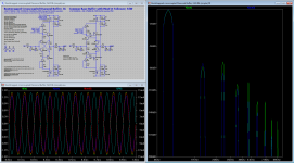
as the Buffer isn´t that powerfull I simmed a bit more to increase drive capability.
I added two bipolars connected in CFP-style with the output transistors and fudged the resistor values accordingly.
Mostly it sims as expected.
The current through the resistors R7/R8 is increased to ~44mA (or whatever value one likes to design)
THD remains at those ridicolously low levels with a nice decay spectrum.
It can drive lowohmic loads like HPs.
The output impedance is low at 2R8.
It puts out 1Vrms 1kHz into a 15R load sims with less than 0.02% THD.
There´s an issue though with the sim.
Yesterday it only simmed with lower input frequencies and didn´t sim when the frequency was raised to 100kHz.
Sims with lower freqs showed a HF-oscillation + harmonics.
Without any change, today the 100kHz sim runs through without.
But as You may see from all plots there are HF-peaks, independent of the load (300R or 10k).
Weird though that the peaks occur to be somehow synchronous to the input frequency.
At 1kHz it occurs at 6.5/13MHz, with 20kHz it peaks at 135/270MHz and for 100kHz the peaks are at 650/1300MHz.
So in all plots this factor of 65x occurs.
I think its an issue of LTspice as it can´t be dealt with by compensation methods.
Anybody an idea whats going on here?
The Sim file is attached for own tests.
jauu
Calvin
Attachments
-
 Bootstrapped crosscoupled Diamond CFP Buffer.gif72.1 KB · Views: 285
 -
Bootstrapped crosscoupled CFP Diamond Buffer - JG.asc11.8 KB · Views: 42
-
 Bootstrapped crosscoupled Diamond CFP Buffer - THD 100k 1V 300R.gif47.5 KB · Views: 64
 -
 Bootstrapped crosscoupled Diamond CFP Buffer - THD 100k 1V 10k.gif47.2 KB · Views: 61
 -
 Bootstrapped crosscoupled Diamond CFP Buffer - THD 20k 1V 300R.gif47.5 KB · Views: 68
 -
 Bootstrapped crosscoupled Diamond CFP Buffer - THD 20k 1V 10k.gif47.9 KB · Views: 59
 -
 Bootstrapped crosscoupled Diamond CFP Buffer - THD 1k 1V 300R.gif47.4 KB · Views: 79
 -
 Bootstrapped crosscoupled Diamond CFP Buffer - THD 1k 1V 10k.gif46.6 KB · Views: 227
 -
 Bootstrapped crosscoupled Diamond CFP Buffer - THD 1k 1V 15R.gif54.3 KB · Views: 69
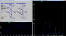
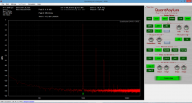
Yesterday night, I made a mistake in stating the loading ability of the circuits, so here some graphs and calculations. The series resistor is now 1mOhm (there I made the mistake) and the parallel resistor (load) is now 10ohm. In the FFT you see that the amount of distortion goes to about the same level for both circuits (near -80dB @ 13.9mA(out) peak) in the other graph you can see that the voltage drop on the output of the 'common base' circuit is very low compared to the 'diamond' circuit (22mV for the 'common base' and 161mV for the diamond at 1.41V at the output)
The 'common base' circuit drops 22mV at 13.9mA = 1.5ohm
The 'diamond' 161mV at 13.9mA = 11.5ohm
To be on the safe side I would estimate that the 'common base' circuit is usable for loads as low as 15ohm and the 'diamond' circuit for loads down to 115ohm.
One more note, when looking at the THD graphs you will see that the 'common mode' circuit gives nice series of values (always decaying) than the 'diamond' circuit, but the difference is small.
P.s. The bias is still 11mA, thus the 15mA is delivered while in AB (and I see now that the CFP mod gives about the same FFT (for full load) at a (lots) higher bias).
The 'common base' circuit drops 22mV at 13.9mA = 1.5ohm
The 'diamond' 161mV at 13.9mA = 11.5ohm
To be on the safe side
I would estimate that the 'common base' circuit is usable for loads as low as 15ohm and the 'diamond' circuit for loads down to 115ohm.One more note, when looking at the THD graphs you will see that the 'common mode' circuit gives nice series of values (always decaying) than the 'diamond' circuit, but the difference is small.
P.s. The bias is still 11mA, thus the 15mA is delivered while in AB
(and I see now that the CFP mod gives about the same FFT (for full load) at a (lots) higher bias).Attachments
Last edited:
The buffer from post 9986 is working.
I made some small changes because i had the parts ( or rather not ).
The CCS J-Fet is a J112 degenerated with 6.8kOhm.
I use a 1uF instead of 4.7uF in the bootstrap.
The offset trim within one CCS works.
In my case i had to tame the negative side.
Initial offset was 200mV.
Now it is plus-minus 10mV so there are some small thermal issues.
I will let the circuit run in for a while and see what happens.
I will also publish some measurements.
I added 120 Ohm gate stoppers and now the buffer is stable.
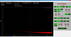
In the sweet spot of my QA400 i measure -107dB distortion.
That is my limit on this little maschine.
As predicted distortion is exponential falling to higher orders, good.
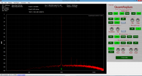
Then i balasted the output with a cuel 33 Ohm BEFORE the 10 Ohm output resistor.
Now distortion is around 0.4%, again exponential falling.
The volume came down from -6.05dB ( 498mV ) to -8.19dB ( 389mV ) with 33Ohm ballast.
From there you can calculate the output impedance and the damping factor.
400mV on my 35 Ohm AKG K550 is a hell of a lot of noise.
55mV give 90dB so 400mV is near 100dB.
I think this buffer can be used on low impedance phones.
It will likely produce a tube like sound, at laest on peaks.
Intermodulation is low.
This buffer is a bit more noisy in the bass then the diamond buffer.
I think that comes from the 500 Ohm input resistors.
This is not an audible problem the A Weighted curve shows.
In the sweet spot of my QA400 i measure -107dB distortion.
That is my limit on this little maschine.
As predicted distortion is exponential falling to higher orders, good.
Then i balasted the output with a cuel 33 Ohm BEFORE the 10 Ohm output resistor.
Now distortion is around 0.4%, again exponential falling.
The volume came down from -6.05dB ( 498mV ) to -8.19dB ( 389mV ) with 33Ohm ballast.
From there you can calculate the output impedance and the damping factor.
400mV on my 35 Ohm AKG K550 is a hell of a lot of noise.
55mV give 90dB so 400mV is near 100dB.
I think this buffer can be used on low impedance phones.
It will likely produce a tube like sound, at laest on peaks.
Intermodulation is low.
This buffer is a bit more noisy in the bass then the diamond buffer.
I think that comes from the 500 Ohm input resistors.
This is not an audible problem the A Weighted curve shows.
Attachments
PAGE 1000 is arrived at in this thread ..
Congratulations.
Who will do POST 1000 ?
10 000 of course
You just made post 9991!!! Makes sense, there are at least 20 posts in a page. For me it's page 200 since I have it set to the max posts per page.
So 8 posts from now, someone will make post 10000.
My browser shows 10 messages per page and the "official"
page counter looks the same, interesting.
I guess this is the default condition.
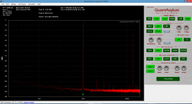
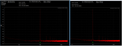
Here is a comparison of the QA400 loop back against the Allison buffer.
There is maybe a tiny bit more K2 and a tiny bit less K3 in the picture with the buffer but thats it.
I am satisfied.
As i told you i can setup the Keantoken so that it even cancels harmonics from the Quant Asylum. We could open up a busyness with repackaged QA400 with over compensated Keantoken in front
Attachments
An offset large a this, some drift and strange noises are hints to parasitic oscillation in many cases.After the oszillation is gone the DC offset is stable.
With 400mV initial it is too big though to be adjusted with the CCss.
There has to be another method.