sorry, I seem to be unable to match your simulation results....
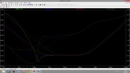
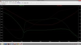
see attached picture, where I used 18V DC input along with a sine wave source (AC=1). The
dark green line is the "simple" circuit (taken from JG's post, circuit 2), the
light green line is a 2nd grade lowpass filter along with R divider to get the output voltage down to 12V, the
dark red line has the upper resistor of that divider replaced with a JFET but only 1st order lowpass filter, and the
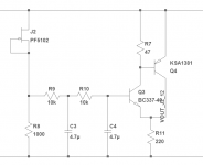
dark blue line has the JFET and 2nd order lowpass filter, as in attached schematic.
The last version has the best behaviour especially at low frequencies. All the circuits converge around -72dB for higher frequencies, with disappearing damping at high frequencies. Here, the simple circuit is a few dB worse than the rest, probably due to the low C-E voltage but thats just a guess. Adding a 4.7uF from output to ground keeps it at -65dB or better.
So I would still claim that by simply putting a JFET instead of the resistor, and a 2nd order lowpass, the circuit is somewhat improved at not much added complexity, and the startup time will be faster too. And, it works with 4.7uF foil caps
see attached picture, where I used 18V DC input along with a sine wave source (AC=1). The
dark green line is the "simple" circuit (taken from JG's post, circuit 2), the
light green line is a 2nd grade lowpass filter along with R divider to get the output voltage down to 12V, the
dark red line has the upper resistor of that divider replaced with a JFET but only 1st order lowpass filter, and the
dark blue line has the JFET and 2nd order lowpass filter, as in attached schematic.
The last version has the best behaviour especially at low frequencies. All the circuits converge around -72dB for higher frequencies, with disappearing damping at high frequencies. Here, the simple circuit is a few dB worse than the rest, probably due to the low C-E voltage but thats just a guess. Adding a 4.7uF from output to ground keeps it at -65dB or better.
So I would still claim that by simply putting a JFET instead of the resistor, and a 2nd order lowpass, the circuit is somewhat improved at not much added complexity, and the startup time will be faster too. And, it works with 4.7uF foil caps
Attachments
Last edited:
I have tested the Kmultipliers with various voltage drops. My results conform within 6db usually to the results obtained by simulating with Cordell or NXP models. Because the BC3x7 are low-quasi-sat transistors, after you are at .6V Vce or so, there is very little improvement in PSRR. It is ONLY for quasi-saturating transistors like the 2N5551 that you need more than a volt or so Vce, and even then they won't perform very well.
Like I said, more filtering will help with the bass, but won't do much for the rest of the spectrum. If you need more bass and less capacitance, you can use a higher-order filter. I have thought about using a 2nd-order filter to increase RF isolation, but I think radiated RF will already be greater than whatever is gained.
seems my simulations are in agreement with your statement
sorry, I seem to be unable to match your simulation results....
see attached picture, where I used 18V DC input along with a sine wave source (AC=1). The
dark green line is the "simple" circuit (taken from JG's post, circuit 2), the
light green line is a 2nd grade lowpass filter along with R divider to get the output voltage down to 12V, the
dark red line has the upper resistor of that divider replaced with a JFET but only 1st order lowpass filter, and the
dark blue line has the JFET and 2nd order lowpass filter, as in attached schematic.
The last version has the best behaviour especially at low frequencies. All the circuits converge around -72dB for higher frequencies, with disappearing damping at high frequencies. Here, the simple circuit is a few dB worse than the rest, probably due to the low C-E voltage but thats just a guess.
So I would still claim that by simply putting a JFET instead of the resistor, and a 2nd order lowpass, the circuit is somewhat improved at not much added complexity, and the startup time will be faster too. And, it works with 4.7uF foil caps
Can this circuit be used instead of the "normal" big smoothing cans in a raw dc psu behind the paradise ?
I mean, can we expect to be able to use 4,7u film caps instead of 10.000uF EL for smoothing ?
This would really open a new window of opportunities...
As for now I know that even the smoothing caps can be "heard" before the shunts...
Stange idea, but R7 ( post 9042 ) could be substituted with a cascode transistor.
Replaced it with a JFET (no other changes), and the behaviour improved ~5dB at low frequencies, no change at high frequencies.
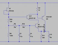
sorry, I misunderstood you, and powered up again for one more simulation. cascoding the NPN with another NPN between the collector and the base of the power PNP improves the damping from -72dB to about 90dB, up to 100kHz or so.... but the simplicity is kind of gone now.....
Attachments
Hesener, use Cordell's model for the KSA1381, to be sure the model isn't fudged. Also, if your reference impedance is too high, C-B leakage will decrease LF PSRR. Another thing I forgot.
That's the idea, as long as your load current is within the nominal. The idea is for the Kmultiplier to be better or at least no worse than the best lytics, so not really any better than it needs to be. This way it does not cause RF problems or low resonances like an LM317 might. Actually, the Kmultiplier can do better than a huge bank of caps because it has low Zout into the subsonics whereas bite-size caps do not.
I have simulated various Jfets and things there, and the improvement is usually not very good because it must have such low voltage across it. You could put diodes in series with the output emitter, but then that's more joints to solder. Actually, the perfect device for low-voltage current sources is a non-quasisaturating BJT. However using this requires several extra components.
If we increased the voltage drop to 5V or so, we may be able to do better, but the Kmultiplier would no longer be useful for low voltage drop. Is that what you guys want? I have some good ideas to improve PSRR; how much PSRR do you need? More than 60db? Is a few hundred uV of output noise still too much?
How much extra complexity is tolerable? For Joachim's application, the goals seem pretty clear, but are we all talking about the same goal?
Can this circuit be used instead of the "normal" big smoothing cans in a raw dc psu behind the paradise ?
I mean, can we expect to be able to use 4,7u film caps instead of 10.000uF EL for smoothing ?
This would really open a new window of opportunities...
As for now I know that even the smoothing caps can be "heard" before the shunts...
That's the idea, as long as your load current is within the nominal. The idea is for the Kmultiplier to be better or at least no worse than the best lytics, so not really any better than it needs to be. This way it does not cause RF problems or low resonances like an LM317 might. Actually, the Kmultiplier can do better than a huge bank of caps because it has low Zout into the subsonics whereas bite-size caps do not.
Stange idea, but R7 ( post 9042 ) could be substituted with a cascode transistor.
I have simulated various Jfets and things there, and the improvement is usually not very good because it must have such low voltage across it. You could put diodes in series with the output emitter, but then that's more joints to solder. Actually, the perfect device for low-voltage current sources is a non-quasisaturating BJT. However using this requires several extra components.
If we increased the voltage drop to 5V or so, we may be able to do better, but the Kmultiplier would no longer be useful for low voltage drop. Is that what you guys want? I have some good ideas to improve PSRR; how much PSRR do you need? More than 60db? Is a few hundred uV of output noise still too much?
How much extra complexity is tolerable? For Joachim's application, the goals seem pretty clear, but are we all talking about the same goal?
Hesener, you need to state exactly what your goals are and what you are making. That is a regulator, not a C-multiplier, and it apparently has much different design constraints. What are your design constraints? Why not just build a shunt reg, Salas or otherwise? As a regulator, that would probably perform better. What is the combination of features that you see the potential or in the Kmultiplier?
I have ideas for:
1: More PSRR
2: Lower Zout
3: Higher voltage
4: Several amps output
What do you guys want?
Also, is it okay if the mods merge this discussion (starting at post 9000) with the Kmultiplier thread?
http://www.diyaudio.com/forums/powe...ntokens-cfp-cap-multiplier-8.html#post3380593
I have ideas for:
1: More PSRR
2: Lower Zout
3: Higher voltage
4: Several amps output
What do you guys want?
Also, is it okay if the mods merge this discussion (starting at post 9000) with the Kmultiplier thread?
http://www.diyaudio.com/forums/powe...ntokens-cfp-cap-multiplier-8.html#post3380593
Last edited:
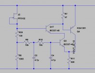
here are the simulation results, comparing the "simple" C multiplier with the more elaborate one. please note this schematic now contains the output cap 10uF
Check the output impedance as well. There is more than PSRR. One main feature of the Kmultiplier is to maintain low Zout into the bass, which is a feat with lytics.
you are right, its no longer a cap multiplier but a hybrid. referencing R8 to the output would reverse that, so the circuit could be developed into a cap multiplier with high voltage drop but good noise isolation. in fact, i just played around with the circuit, no real specification in mind...
personally i have nothing against a little regulation, but that depends entirly on the application
personally i have nothing against a little regulation, but that depends entirly on the application
Cool link, Peter.
Sorry, i did not do much today.
The pass transistor in the cap multiplier with the 4,7uF got really hot and i do not know why.
Frans told me an idea how i can inject a signal ( say a 1kHz sine ) into the multiplier with a transformer so i hope i can generate some FFTs.
It could be oscillation. This is a problem with using these circuits at small currents I've found. I've never had a transistor get hot because of it though. Do you have input and output caps?
DIY Fablabs are now coming in fashion in Germany :
Maker Messe in München ? Make Munich
Dang ! I missed this and I just happened to be here in Munich !
boB