Here is the variety of the K-multiplier i used in the headphone amp. The negative one is build the same way. Do you think it is dimensined resonable ?
Circuit 2 shows a more conventional circuit i would like to build for comparison. It came out of the simulator well. I see the main advantage of circuit 2 in the use of a quite small shunt cap. There is a really small 4.7uF Wima foil so it could work without electrolytics.
Circuit 1 will need a higher input voltage compared to circuit 2.... how about using a CCS instead of the diodes that connect to the base of the NPN? A simple JFET might be enough, and give tons of noise isolation....
The circuits should have very similar voltage drop because of the 17uA base current. 17uA through 3 diodes is 1.2V. 17uA through 68k is also 1.2V.
A CCS won't improve noise isolation because it is the Early effect of the driver that limits that. More filtering for the reference is not an improvement except at bass or subsonics.
A CCS won't improve noise isolation because it is the Early effect of the driver that limits that. More filtering for the reference is not an improvement except at bass or subsonics.
Circuit 1 will need a higher input voltage compared to circuit 2.... how about using a CCS instead of the diodes that connect to the base of the NPN? A simple JFET might be enough, and give tons of noise isolation....
The circuits should have very similar voltage drop because of the 17uA base current. 17uA through 3 diodes is 1.2V. 17uA through 68k is also 1.2V.
A CCS won't improve noise isolation because it is the Early effect of the driver that limits that. More filtering for the reference is not an improvement except at bass or subsonics.
That is exactly true, the circuits where tuned to exactly the same output voltage (the difference in the simulation is only 16mV). (post #9007 left).
Edit: Oops... this is about #9016
") (the output voltages of left and right are about the same). Joachim will build and analyze both lets wait and see...
(the output voltages of left and right are about the same). Joachim will build and analyze both lets wait and see...
Last edited:
Jackinnj, what is the second reg in your example?
The Jung Regulator with LM317 pre-regulator and AD825AR error amplifier.
I do have a preference for making R-C og L-C type of circuits, where the PSU impedance mainly relies on single passive components.
I once made a DAC with a tube rectified power supply. And i must say the blackness and tone colors I got there was truly outstanding.
Tube rectifiers really eliminates diode switching noise.
I once made a DAC with a tube rectified power supply. And i must say the blackness and tone colors I got there was truly outstanding.
Tube rectifiers really eliminates diode switching noise.
I will now build the two circuits, both with 47 Ohm to supply the pass transistors.
I have no problem to understand you Keantoken but you look at this circuit from another angle. For example i have seen other cap multipliers that have massive filtering of the base current. You are the first one that said that filtering is limited by the early voltage ( at higher frequencies ) and i have to digest this.
I have no problem to understand you Keantoken but you look at this circuit from another angle. For example i have seen other cap multipliers that have massive filtering of the base current. You are the first one that said that filtering is limited by the early voltage ( at higher frequencies ) and i have to digest this.
Here is another example with conventional darlington :
Capacitance Multiplier Power Supply Filter
Capacitance Multiplier Power Supply Filter
Here is another example with conventional darlington :
Capacitance Multiplier Power Supply Filter
Using a darlington makes for a larger voltage drop and thus a lower value of the filter resistor (or both, or any of these
)Here is an example of massive filtering :
The LM needs 5V drop and the multiplier is configured for 10% that is a lot to drop and I do not see very great benefits. If you want a absolutely stable voltage, and you are spending all these components, also the complexity, then a Jung 2000 Regulator may be a better bet.
Hi,
I just simmed some ciruits among them those of #9004.
If one wants to improve Ripple rejection without large R and C values or the speed-Up-diode, a cascade of smaller valued RC filters may help similar to #9027.
If in #9004 one omits with the 680R/LED and replaces the 1k/220µ with two RCs of 100R/100µ the behaviour is already very similar. A third 100R/100µF is better in nearly every aspect. Less noise, lower DC- and AC-impedance and faster output voltage rise.
jauu
Calvin
Hi,
I just simmed some ciruits among them those of #9004.
If one wants to improve Ripple rejection without large R and C values or the speed-Up-diode, a cascade of smaller valued RC filters may help similar to #9027.
If in #9004 one omits with the 680R/LED and replaces the 1k/220µ with two RCs of 100R/100µ the behaviour is already very similar. A third 100R/100µF is better in nearly every aspect. Less noise, lower DC- and AC-impedance and faster output voltage rise.
jauu
Calvin
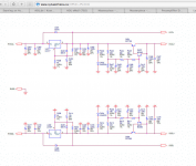
The circuit #9004(left) was updated to the one in #9007(left, out5). I did simulate this with a split filter resistor (R24 from 68K to 2x 33K) and 2 2.2u capacitors, but this makes near to no difference. The #9007(left, out5) will be tested, and was selected, due to small capacitor (can be a foil SMD type) and simple (low component count
).Just did a quick check using the simulator. Splitting the R and the C lowers the ripple at the C by 16dB, it lowers the output ripple by only 1.2dB
Last edited:
The circuits should have very similar voltage drop because of the 17uA base current. 17uA through 3 diodes is 1.2V. 17uA through 68k is also 1.2V.
ok thanks,
A CCS won't improve noise isolation because it is the Early effect of the driver that limits that. More filtering for the reference is not an improvement except at bass or subsonics.
... hence good reason to increase the voltage across the transistors, depending on the device this will improve early voltage quite a bit. Still think that with a quietly-fed reference and 2nd/3rd order lowpass filter (as Calvin suggests) PLUS some more voltage drop across the pass devices, the results should be even better....
Switching back to the raw headphone it sounded like plastic, that coloration most come from the membrane.
When my son comes back from vacation i will show you how i set up Foobar to make that happen.
Maybe this could sove the problem one day...
ok thanks,
... Still think that with a quietly-fed reference and 2nd/3rd order lowpass filter (as Calvin suggests) PLUS some more voltage drop across the pass devices, the results should be even better....
But then it is no longer a simple capacitor-multiplier and it starts to get the complexity of a Jung regulator. The design goal, set beforehand, was a capacitor multiplier (to keep things simple).
The simple circuit shown has, easily, -85dB PSRR at 10KHz (2nd harmonic at -130dB) and -100dB at 100Khz (2nd harmonic at -130dB). This all with an input ripple of 3Vpp. The numbers improve significantly when lowering the input ripple (in simulation, Joachim will do the test).
I have tested the Kmultipliers with various voltage drops. My results conform within 6db usually to the results obtained by simulating with Cordell or NXP models. Because the BC3x7 are low-quasi-sat transistors, after you are at .6V Vce or so, there is very little improvement in PSRR. It is ONLY for quasi-saturating transistors like the 2N5551 that you need more than a volt or so Vce, and even then they won't perform very well.
Like I said, more filtering will help with the bass, but won't do much for the rest of the spectrum. If you need more bass and less capacitance, you can use a higher-order filter. I have thought about using a 2nd-order filter to increase RF isolation, but I think radiated RF will already be greater than whatever is gained.
Actually, the very best way by far to increase RF isolation from the input is an RC at the input with Fc at 100KHz. This works out to a 4.7R+330n RC filter, or a 1R+1.5u RC. The 1R+1.5u RC would be highly advantageous because 1R is usually around the right value for damping rails.
Last edited:
Cool link, Peter.
Sorry, i did not do much today.
The pass transistor in the cap multiplier with the 4,7uF got really hot and i do not know why.
Frans told me an idea how i can inject a signal ( say a 1kHz sine ) into the multiplier with a transformer so i hope i can generate some FFTs.
Sorry, i did not do much today.
The pass transistor in the cap multiplier with the 4,7uF got really hot and i do not know why.
Frans told me an idea how i can inject a signal ( say a 1kHz sine ) into the multiplier with a transformer so i hope i can generate some FFTs.