Good that you like it.
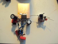
I am happy that my hands are still steady enough at the age of 55 to do something like that.
I have studied your cap multiplier for some time now but never used it until now.
I just had a long Skype with Frans, our PSU Guru and he had some ideas to " improve" it.
I build a proto but still i am not 100% convinced if it is any better then yours.
I will publish some measurements and circuits over the weekend.
Considering the enormous work done by Salas and Frans i am not in the mood to design another shunt. I feel more comfortable with series regulation, cap multipliers and passive filtering. I also got a bit tired about conventional transformer and rectifier circuits so i will try some AC/DC converters to make the raw DC.
Best thing you can do is inject 25mA 1kHz. current into the power supply + or - rail and observe the harmonics on the supply rail -- this came about as a suggestion by one of the commentators to the article for Linear Audio. More predictive value.
Guess which regulator sounds better:
An externally hosted image should be here but it was not working when we last tested it.
or
An externally hosted image should be here but it was not working when we last tested it.
I saw that and think it is one key to success.
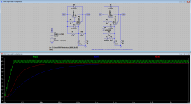
Here is an early simulation of two circuits.
The second simulation shows what happens when the 10uF at the output is taken away.
The second two circuits are not totally identical to the first ones but it shows that small differences can have a huge effect even in very simple circuits.
Here is an early simulation of two circuits.
The second simulation shows what happens when the 10uF at the output is taken away.
The second two circuits are not totally identical to the first ones but it shows that small differences can have a huge effect even in very simple circuits.
Attachments
Alright, I'm excited to see someone's idea for the Kmultiplier. Let me address them:
1: D4xH11 output: The very large capacitances of a large output like this will decrease RF PSRR, which is one of the main ideas of the Kmultiplier. Output inductance will also increase, which shifts the rails away from their inherent self-damping point. Max inrush will increase, but this is only necessary if you use a lot of capacitance at the output. Transient recovery will also be worse. The D4xH11 are actually quite fast; I can't say whether there is a better device I would choose.
2: R8 is a great idea. It gets the required voltage drop without losing RC effectiveness or DC stability. This is not an absolute improvement, but it allows the reference C to be a bit smaller.
3: The higher harmonics on my version may be due to the higher output voltage, even though just a few hundred mV. Try matching the voltage drop of both versions, because Vce does matter quite a lot. The harmonics really only reflect the degree of Vcesat, which will depend on voltage drop which should be adjusted for the application.
I am going to investigate these ideas and see what improvements or drawbacks they may have. I think the reason I didn't use #2 in the first place was because I wasn't using high Hfe drivers, but now that I am, maybe it's a good idea.
Last edited:
My question is, what would you improve and why? There are many ways to customize the Kmultiplier, so knowing what is wanted helps. So far I have simply tried to achieve the best combination and balances of specs.
EDIT: Just remembered, the diodes are there to improve sag rejection, because it causes the Kmultiplier to track only the peaks of the input. This only works if the diode has very small bias current. Sag rejection is a dynamic mechanism that won't show up on AC plots.
EDIT: Just remembered, the diodes are there to improve sag rejection, because it causes the Kmultiplier to track only the peaks of the input. This only works if the diode has very small bias current. Sag rejection is a dynamic mechanism that won't show up on AC plots.
Last edited:
Alright, I'm excited to see someone's idea for the Kmultiplier. Let me address them:
1: D4xH11 output: The very large capacitances of a large output like this will decrease RF PSRR, which is one of the main ideas of the Kmultiplier. Output inductance will also increase, which shifts the rails away from their inherent self-damping point. Max inrush will increase, but this is only necessary if you use a lot of capacitance at the output. Transient recovery will also be worse. The D4xH11 are actually quite fast; I can't say whether there is a better device I would choose.
2: R8 is a great idea. It gets the required voltage drop without losing RC effectiveness or DC stability. This is not an absolute improvement, but it allows the reference C to be a bit smaller.
3: The higher harmonics on my version may be due to the higher output voltage, even though just a few hundred mV. Try matching the voltage drop of both versions, because Vce does matter quite a lot. The harmonics really only reflect the degree of Vcesat, which will depend on voltage drop which should be adjusted for the application.
I am going to investigate these ideas and see what improvements or drawbacks they may have. I think the reason I didn't use #2 in the first place was because I wasn't using high Hfe drivers, but now that I am, maybe it's a good idea.
1: 2SA1930 may be a better choice (Ft 300Mhz (from the top of my head)) Salas opted this one as a improvement for the CCS of the Paradise PSU.
2: When using high values for the filter resistor R24, the Rbe of Q9 is not needed (most probably not wanted).
3: From the graph (post #9007 left), the difference is 16mV (almost equal
") ) For the other (post #9007 right) I think you may be right (although the difference is only 100mV).
) For the other (post #9007 right) I think you may be right (although the difference is only 100mV).One further thing. There is not much point in increasing the RC time constant. It won't improve output ripple because that is determined by the Early effect of the transistors, whereas the reference voltage is much quieter already. PSRR begins to fall below 100Hz. If you are using the Kmultiplier in a power amp, you may want to extend this to 20Hz. However due to the "sag rejection", output ripple may not be as bad as you expect for a conventional circuit.
However it doesn't seem the intent was to lower the LF PSRR, because the reference cap was made much smaller. I wonder why make the cap smaller?
Also, output risetime can become long with a large C, and some circuits don't like slow-rising rails. This is why the LED+680R, to improve turn-on time.
So, considering all this, it seems that the Kmultiplier is difficult to improve without undermining the balance of its features and thus the overall performance.
1: 2SA1930 may be a better choice (Ft 300Mhz (from the top of my head)) Salas opted this one as a improvement for the CCS of the Paradise PSU.
2: When using high values for the filter resistor R24, the Rbe of Q9 is not needed (most probably not wanted).
I hesitate to use the C5171/A1930 above 400mA because of the beta droop, but you could parallel them, and that would definitely be best - I keep forgetting how simple it is to parallel transistors.
You can use a very large resistor and just rely on the base current to set up bias, but this makes the circuit much more dependent on temperature and Hfe. This is not necessarily a bad thing, but when troubleshooting it means there will be more questions. Furthermore, like I said before, if you do this you are losing the essential features of the Kmultiplier. For one thing, the reference impedance can hurt output impedance if you use a large resistor and small cap.
As simple as it is, the Kmultiplier is really a very optimized circuit. Extending PSRR below 100Hz is probably not a good idea for a power amp in any case because the Kmultiplier needs to be able to track the rails, so that it doesn't saturate or clamp in order to correct an emergency situation. This is actually why the Fc is not set too low.
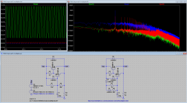
But there is a difference, the implementation here is intended for a preamp and 100mA (or up to a few 100mA's) will be enough. Absolute voltage stability is not what will be asked from the supply, but the 100Hrz ripple goes from 3mVpp to 8mVpp when changing the capacitor from 4.7u to 1u (in #9007 left). (the input supply ripple as simulated is 3Vpp (unrealistically high, but hey this is a simulation). The simulation uses a 300mA load, in this condition the PSRR at 100Hz is this 3Vpp/3mVpp = 1000x. The startup time for #9007 left is 1.4Sec and for #9007 right is 0.5Sec (two LED's where used to accommodate for the larger voltage drop wanted).
Okay, so you are customizing it for your application rather than trying to improve the whole scheme. Now I see.
Simulation accuracy is not a linear phenomenon. Simulating at 3V ripple to predict the circuit behavior in real life at 2V is not realistic because you are driving the transistors into saturation which would never happen with 2V ripple. It is interesting as a worst-case scenario but behavior at normal conditions is what we hear.
Simulation accuracy is not a linear phenomenon. Simulating at 3V ripple to predict the circuit behavior in real life at 2V is not realistic because you are driving the transistors into saturation which would never happen with 2V ripple. It is interesting as a worst-case scenario but behavior at normal conditions is what we hear.
Last edited:
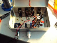
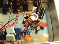
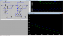
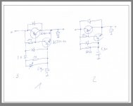
Here is the variety of the K-multiplier i used in the headphone amp. The negative one is build the same way. Do you think it is dimensined resonable ?
Circuit 2 shows a more conventional circuit i would like to build for comparison. It came out of the simulator well. I see the main advantage of circuit 2 in the use of a quite small shunt cap. There is a really small 4.7uF Wima foil so it could work without electrolytics.
Circuit 2 shows a more conventional circuit i would like to build for comparison. It came out of the simulator well. I see the main advantage of circuit 2 in the use of a quite small shunt cap. There is a really small 4.7uF Wima foil so it could work without electrolytics.
Attachments
I estimate the current gain of that to be around 28k depending on loading. The reference impedance is divided by the Kmultiplier current gain like in a conventional C-multiplier. A 1.4k impedance will cause an extra 50mR output resistance. With a 68k filter resistor, that works out to 2.4R DC output resistance.
Since your Fc is set to .5Hz, the point where reference impedance falls below 1.4k will be around 24Hz; below this point output impedance will be capacitive.
So, accounting for everything it looks like your circuit will work fine. However, the 100R resistor affects output resistance significantly. I chose 47R because usually it is best to bias the driver as high as you can, unless your load has very low current. And in that case, you might as well just hang a resistor off the output to get at least 20mA load to put it in more linear operation. If you don't want the extra loading, choosing this resistor is a balancing act and you will not necessarily get output resistance values comparable to good lytics. At the same time, the extra dampening may be appreciated as long as your output lytics are large.
EDIT: Actually, biasing the driver low may cause oscillation. That is the other reason I made this resistor 47R. Even if it doesn't outright oscillate, it will aggravate the Q of any adjacent RF resonances. I would not go above 150R.
Last edited:
I have to read your post carefully to understand it.
I've been getting this a lot lately, but I'm not quite sure what it means. I try to be direct, unambiguous and non-obfuscating. But I also try not to say something the same way twice. If a person can read my post without thinking, it is less likely they will understand my message. So what I want to know is, how can I improve my writing?
I tested circuit 1 with a 220 Ohm resistor.
With 12V that is around 55mA.
The Headphone amp draws 25mA idle and i wanted some leeway.
I was referring to the 100R resistor at the driver collector. The load resistance shouldn't matter except as a load.
So, accounting for everything it looks like your circuit will work fine. However, the 100R resistor affects output resistance significantly. I chose 47R because usually it is best to bias the driver as high as you can...
This is agreeing with my experience, in the above simulations I used 47R and I would never advice any above 100R at this position.